Do you have a question about the SEW MOVIDRIVE MDX61B and is the answer not in the manual?
Guidance on how to effectively read and utilize this manual for optimal understanding.
Explanation of the format and meaning of safety notes and warnings presented throughout the document.
Broad safety guidelines applicable to the operation and handling of the equipment.
Identifies the intended audience qualified to install, operate, and service the unit.
Specifies the intended applications and operational limits for the drive inverters.
Guidelines for the safe transport and storage of the unit to maintain its integrity.
Instructions and regulations for the correct installation of the drive units.
Procedures and safety measures for establishing proper electrical connections.
Requirements and methods for safely disconnecting power and electronic connections.
Guidance on safe operation, including monitoring and protection devices.
Explains unit identification, nameplate details, and the standard scope of delivery.
Detailed list of components included in the standard scope of delivery for various unit sizes.
Detailed illustration and description of the physical layout for size 0 units.
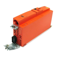
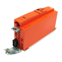
Detailed illustration and description of the physical layout for size 1 units.
Detailed illustration and description of the physical layout for size 2S units.
Detailed illustration and description of the physical layout for size 2 units.
Detailed illustration and description of the physical layout for size 3 units.
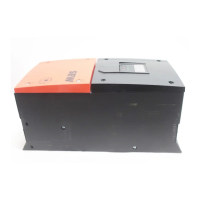
Detailed illustration and description of the physical layout for size 4 units.
Detailed illustration and description of the physical layout for size 5 units.
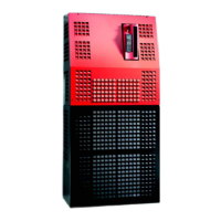
Detailed illustration and description of the physical layout for size 6 units.
Detailed illustration and description of the physical layout for size 7 units.
Comprehensive guidelines for installing the core unit of the MOVIDRIVE® system.
Step-by-step instructions for detaching and attaching the operating keypad.
Procedures for safely removing and reinstalling the unit's front protective cover.
Details on UL compliance, terminal tightening torques, and short-circuit current ratings.
Instructions on how to install shield clamps for power sections, particularly for size 0.
Safety instructions and requirements for installing touch guards on power terminals for IP20 protection.
Essential diagrams illustrating the electrical connections for the basic unit's power section and brake.
Guidance on selecting and assigning appropriate braking resistors, chokes, and filters for various units.
Instructions for connecting the MOVIDRIVE® units to the system bus (SBus).
Procedures for establishing communication via the RS485 interface for unit networking.
Details on connecting single-ended HTL encoders using the DWE11B/12B adapter.
Instructions for connecting the UWS21B adapter for RS232 communication to a PC.
Steps for connecting the USB11A adapter for PC communication and software setup.
Overview of compatible option cards and their placement in the unit's slots.
Procedures and precautions for safely installing or removing option cards.
Guidelines for connecting encoders and resolvers, including installation notes and shield management.
Detailed terminal functions and connection specifics for the DEH11B HIPERFACE® encoder option.
Detailed terminal functions and connection specifics for the DEH21B absolute encoder option.
Detailed terminal functions and connection specifics for the DEU21B multi-encoder card option.
Detailed terminal functions and connection specifics for the DER11B resolver option.
Instructions for connecting external encoders to the X:14 connector on specific options.
Procedures for connecting various encoder types to the DEH11B option.
How to use connector X14 for incremental encoder simulation output.
Instructions for establishing master/slave connections between MOVIDRIVE® units using X14.
Detailed terminal functions and connection specifics for the DIO11B input/output card option.
Detailed terminal functions and connection specifics for the DFC11B CAN-bus interface option.
Fundamental guidelines and requirements for initiating the drive's startup process.
Step-by-step procedure for performing startup using the DBG60B keypad.
Overview of tasks and capabilities provided by the MOVITOOLS® MotionStudio software.
Instructions on how to start the motor using analog setpoints and fixed setpoints.
A comprehensive list of all configurable parameters with their settings and descriptions.
Explanation of the 7-segment display and basic status indicators on the unit.
Details on keypad assignments and functions, including parameter and user menu operations.
Information on the memory card for storing and transferring configuration data.
Guidance on accessing and interpreting error messages stored in the fault memory.
A comprehensive list of error codes, their causes, and recommended measures for resolution.
Information on contacting SEW-EURODRIVE service for repairs and support.
Recommended procedure for units stored for extended periods to maintain service life.
Guidelines for environmentally responsible disposal of the unit and its components.
Information on product certifications and compliance standards.
Key technical specifications applicable to all MOVIDRIVE® MDX60B/61B inverters.
Technical data for the AC 400/500 V series inverters.
Specific technical data and specifications for size 0 units in the AC 400/500 V series.
Specific technical data and specifications for size 1 units in the AC 400/500 V series.
Specific technical data and specifications for size 2S and 2 units in the AC 400/500 V series.
Specific technical data and specifications for size 3 units in the AC 400/500 V series.
Specific technical data and specifications for size 4 units in the AC 400/500 V series.
Specific technical data and specifications for size 5 units in the AC 400/500 V series.
Specific technical data and specifications for size 6 units in the AC 400/500 V series.
Specific technical data and specifications for size 7 units in the AC 400/500 V series.
Technical data for the AC 230 V series inverters.
Specific technical data and specifications for size 1 units in the AC 230 V series.
Specific technical data and specifications for size 2 units in the AC 230 V series.
Specific technical data and specifications for size 3 units in the AC 230 V series.
Specific technical data and specifications for size 4 units in the AC 230 V series.
Detailed technical specifications related to the electronic components and interfaces of the unit.
Dimension drawings for MOVIDRIVE® MDX60B units.
Dimension drawing specifically for MOVIDRIVE® MDX60B size 0S.
Dimension drawing specifically for MOVIDRIVE® MDX60B size 0M.
Dimension drawings for MOVIDRIVE® MDX61B units.
Dimension drawing specifically for MOVIDRIVE® MDX61B size 0S.
Dimension drawing specifically for MOVIDRIVE® MDX61B size 0M.
Dimension drawing specifically for MOVIDRIVE® MDX61B size 1.
Dimension drawing specifically for MOVIDRIVE® MDX61B size 2S.
Dimension drawing specifically for MOVIDRIVE® MDX61B size 2.
Dimension drawing specifically for MOVIDRIVE® MDX61B size 3.
Dimension drawing specifically for MOVIDRIVE® MDX61B size 4.
Dimension drawing specifically for MOVIDRIVE® MDX61B size 5.
Dimension drawing specifically for MOVIDRIVE® MDX61B size 6.
Dimension drawing specifically for MOVIDRIVE® MDX61B size 7.
Technical specifications for various optional interface and braking resistor modules.
EC Declaration of Conformity for the MOVIDRIVE® series products.
EC Declaration of Conformity for MOVIDRIVE® units equipped with DFS11B/DFS21B options.
EC Declaration of Conformity for MOVIDRIVE® units equipped with DCS21B/DCS31B options.
| Protection Class | IP20 |
|---|---|
| Storage Temperature Range | -25°C to +70°C |
| Control Type | V/f control, Vector control |
| Communication Interfaces | PROFIBUS, CANopen, DeviceNet, Ethernet |
| Output Frequency | 0 Hz to 300 Hz |
| Cooling Method | Forced ventilation |
| Relative Humidity | 5% to 95% (non-condensing) |