4
EN
1
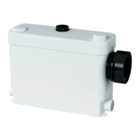
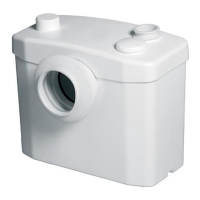
DESCRIPTION
The SANIPACK
®
isacompactmacerator/pumpespecially
designedtoacceptthewastewaterfromawallhungtoiletor
back-outlettoilet.
The SANIPACK
®
willpumpawaythewastefromatoilet,
asinkandashowerforresidentialapplications.Installed
andusedcorrectly,theSANIPACK
®
willgiveconsistentand
reliableservice.
Themaceratingunitalsoconsistsofthreemajorparts:the
containerwhichhousestheoperatingmechanism;apressure
chamberwhichautomaticallyactivatesanddeactivates;
theinductionmotorwhichdrivesthecuttingbladeandthe
impeller.Themaceratingunitcansimultaneouslyreceive
wastewaterfromseveralsanitaryfixtures,e.g.sink,shower,
butonlyonewaterclosetperunit.
Maceratingunitsaredesignedforthedisposalofhuman
waste,toiletpaperandwater.Theyarenotintendedto
beusedforthedisposalofkitchenwaste,neitherarethey
intendedtobeusedforthedisposalofwastewaterfrom
suchpumpappliancesasdishwashersandclotheswashers.
Maceratingsystemmustdischargeintoaminimum3/4-inch
sanitarydrainagepipe.Themaceratingsystemwillpumpup
to15feetvertically,witha1/4"perfootgravityfall(minimum)
constantlythroughoutthehorizontalruntothepointof
discharge.
Ifyourequireaverticalliftitshouldprecedeany“horizontal”
runandshouldcommenceasnearaspossibletothe
dischargeelbow.Onceyouhavestartedthehorizontalrun,
youcannotchangedirectionsinanupwardverticalmanner.
Please note the following warning signs:
«
» Possibledangertopersonnel,
«
» Warningofpossibleelectricalhazard.
«WARNING» Thisisageneralwarningthatfailuretofollow
instructionscouldresultinpoorfunctioningoftheunit.
2
LIST OF ACCESSORIES INCLUDED-
seedrawings.
3
DIMENSIONS-seedrawings.
4
TECHNICAL DATA
Application 1 toilet + sink
+ Shower
TypeP30
MaximumVerticalPumping15Ft
Voltage120V
Frequency60Hz
Maximumcurrentconsumption4.5A
Max.Temperature104°F
DegreeofprotectionIP44
NetWeight12Lbs
WARNING:Onlyinstallationsconformingtotheabove
specificationsareacceptable.
5
PERFORMANCE CURVE-seedrawings.
6
VERTICAL/HORIZONTAL PUMPING
COMBINATIONS-seedrawings.
7
INSTALLATION
SANIPACK
®
isdesignedtofitbehindpanelingorwithinthe
wall,andshouldbeinstalledbyaqualifiedperson.
WARNING: Themaceratormustbeconnectedtoawallhung
orback-outlettoiletwhichitsoutletmustbehigherthanthe
inletofthemacerator(7-1/2”CL).Notethatthedrainpipe
comingoutfromthetoiletandgoingintotheconnectionofthe
maceratorshouldhavetheproper1/4”perfootgravityfall.
Themaceratorhasfasteningspreventingitturningorfrom
moving.
7a
EXAMPLE OF INSTALLATION
Seedrawings
7a1
7a2
7a3
.
WARNING: Provideanaccesspanelofthefollowing
dimensionstoenabletheunittoberemovedfor
possibleservice:
L=20”xH=16½” if the side inlets are not used
L=24”xH=16½” if the side inlets are used
WARNING: A screwdriver or other tool should be
required to remove the access panel.
7b
CONNECTION TO THE TOILET
Theflexiblecouplingisdesignedtoaccepta4”PCVpipe
drainingfromthetoiletconnection.Makesuretogreaseor
lubricatewithwaterorliquidsoapwheninsertingthepipe.
WARNING:Thetoiletmustbeinstalledatalevelprovidinga
dropofatleast¼”perfootintothemacerator.
7c
CONNECTION TO SIDE-INLETS
(SHOWER AND SINK)
•Tomaketheconnectiontothesideinlets,useconnector
E
or
E’
.Secureitwithclamps
B
and
K
.
•Plugtheunusedinletwithblankingplug
J
aftergreasing
thejoint.
WARNING:
Ensurewhenconnectingashowertothemaceratingunit
thattheundersideoftheshowertrayisraisedbyatleast
6inches(min.)fromthefloor.
7d
CONNECTION OF A VENT SYSTEM
Themaceratingunitmustbevented.Ithas2inletsonthe
topofthecover:a1½”capandaholeofsmallerdiameter.
Theunitmustbeconnectedtoaventsystemaccordingto
theplumbingcodes.Putthewasteinlet(provided)onthe
capandclampitdown.then,connecttheventpipe.Note
thethatallfixturesconnectedtothesystemmustalsobe
vented.
WARNING: Do not use an air admittance valve or a
mechanical spring-loaded venting device, as these devices
are one-way valves. The air pressure in and outside the
macerating unit must be equal, a “cheater” vent will
obstruct the airflow one direction.
Note: thesmallerdiameter½holemustbepluggedwitha
plasticcapsupplied
G
.
7e
CONNECTION OF THE DISCHARGE PIPE
Theplasticdischargeelbow/checkvalveassemblyshould
beinserted(longend)intotherubberhoselocatedonthe
topofthelid.Thestep-downrubberfittingshouldthen
beinsertedatthedischargesideoftheelbowassembly
andsecuredwiththeprovidedmetalclamps.Thestep-
downrubberfittingmayneedtobecutdependingonthe
dischargepipediameter.Threemetalclampsshouldbe
usedtosecureallfittings.
Installa“full-port”ballorgatevalveandaunioninthe
dischargepipeinordertofacilitatetheremovalofthe
maceratingunit.Placetheunionorhoseconnectorthenthe
valveatthelowerportionofthedischargepipe.
Ifyouwishtheunittopumpverticallyandhorizontallyyou
maycalculatethat3feetofverticalliftisequivalentto30
feetof“horizontal”run.
10514 126 SANIPACK US 062012.indd 4 10/07/12 14:22
 Loading...