EN
18
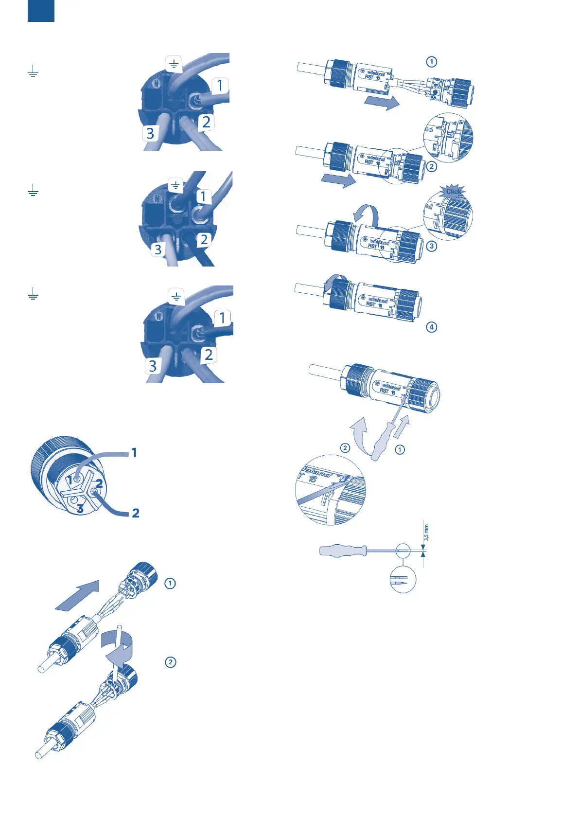
Sanifos with Sanipump GR/VX Single-phase version:
: Green/Yellow wire
Position 1: Brown wire
Position 2: Blue wire
Position 3: White wire
Sanifos with Sanipump GR/VX Three-phase version:
: Green/Yellow wire
Position 1: Brown wire
Position 2: Black wire
Position 3: Grey wire
Sanifos with Sanipump SLD (single- or three-phase version):
: Green/Yellow wire
Position 1: Black wire
Position 2: Grey wire
Position 3: Brown wire
Note: The terminal blocks are already mounted on the Sanicubic pump
cables.
4.2.3 Connectors wiring for floats (Sanifos)
Follow this wiring diagram:
Connect the 2 wires to slots 1 and 2, re-
gardless of colour. It is only important to
respect these two locations.
The wiring is identical for the 3 oats.
4.2.4 Using the terminal blocks
Tightening torque: 0,5 Nm
(DIN 5264 A)
4.2.4.1 Assembling the connector
4.2.4.2 Closing the connector
Tightening torque: 1,5 – 2 Nm
4.2.4.3 Opening the connector