EN
20
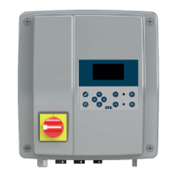
Three-phase version:
NO dry contact
NC dry contact
External alarm
5. COMMISSIONING
5.1 START-UP CONFIGURATION
At the rst start-up, it may be necessary to congure the box by select-
ing the connected station using the and keys:
- the installation tank: [Sani]Cubic 1, [Sani]Cubic 2, [Sani]Fos 500,
[Sani]Fos 610 or [Sani]Fos 1300,
- the type of pump: Brushless, Grinder, Vortex or Solida.
Note: In case of an error or a change in the installation, it is possible to
access this menu (see
10.1Returntothestart-upscreen
)
The operating parameters must then be selected: date, time, language
and brightness of the display.
Note: The date and time must be set correctly for alarm management,
alarm history and maintenance frequencies.
For each conguration screen,
validate the selected setting by
pressing the validation button.
On the last screen (see oppo-
site), press the conrmation
button one last time to start the
Smart box operation.
5.2 CHECKS TO BE CARRIED OUT FOR THE
COMMISSIONING OF A SANIFOS LIFTING STATION
• Set the language, date and time.
• Dene the use of the station: Individual, Collective or Commercial.
• Check that the quick connectors are correctly connected to the
Smart unit.
• Check that the led on both pumps are green.
• Check the power supply voltage on the display.
• Fill the tank with water via the connected sanitary appliances.
• Check that the pumps switch on automatically at the set water level.
• Check that the water operating intensity of the pumps, shown on the
display, is between
– 4 and 7 A with Sanipump GR, Sanipump VX (single-phase and
three-phase), Sanicubic 1, Sanicubic 2, Sanicubic 2 VX three-phase,
– 6 and 12 A with Sanicubic 1 VX single-phase, Sanicubic 2 VX sin-
gle-phase,
– 7 and 10 A with Sanipump SLD single-phase,
– 3 and 5 A with Sanipump SLD three-phase.
• Check the correct operation of the motors in forced operation.
• Check that the wired alarm box is switched on.
• Check the level of water in the tank at the end of the cycle:
– Sanicubic: the water level must be below the longest dip tube.
– Sanifos with Sanipump VX or Sanispump SLD: the water level
must be above the pump cover plate.
– Sanifos with Sanipump GR: the water level is +/- 10 cm from the
bottom of the tank.
• Set the delay time accordingly.
• Set the delay for the start of the auxiliary pump. Measure the dura-
tion of an ON-OFF cycle and enter a value equal to at least 2 times
the ON-OFF cycle value.
• Check that the data has been correctly recorded by the Smart box
(log, pumping time…).
6. OPERATION
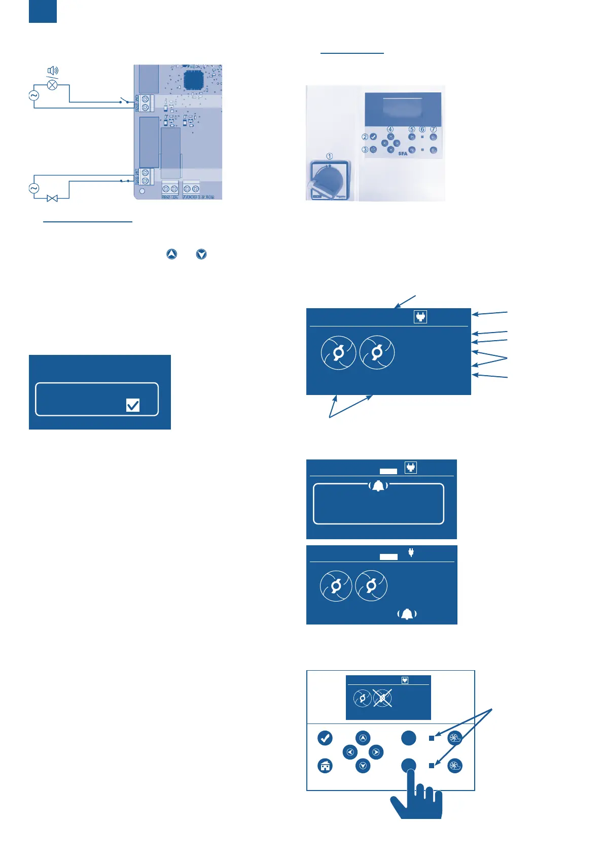
6.1 PRESENTATION OF THE FRONT OF THE BOX
6.1.1 Key identification
Current switch
Enter Key
Back
Navigation
Activation/deactivation of the
pumps
Pump operation
indicator light
Forced operation of pumps
6.1.2 Operating lights
The light is green when the pump is activated.
The light is red when the pump is deactivated (by a manual lockout or
automatically following a fault).
6.2 USING THE CONTROL BOX
6.2.1 On screen display
6.2.1.1 Normal operation
Time
Pump current
Power output
SC_2VX
6.2.1.2 Alarm display
SC_2VX
ALARM
Alarm indicator in real time,
with identication of the
problem detected for quick
maintenance.
A special window giving the
alarm type and the alarm
time remains open for some
time.
As soon as the fault disap-
pears, return to the general
screen on which an alarm
notication appears. To re-
move the alarm notication,
simply press one of the two
forced-on buttons. Details of
the alarms can be consulted
in the alarm log.
6.2.2 Pump activation/deactivation
In the case of maintenance or replacement of a pump, it is possible to
deactivate each pump independently.
indicator light
SC_2VX
P1
P2
SFA
SC_2VX
ALARM
 Loading...