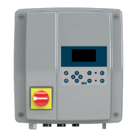
EN
23
SC_2VX
Settings
P_aux start
SC_2VX
Settings>P_aux start
Activation after: 1m05s
• Then press and to select the value.
• Press to conrm the choice.
• Press to return to the main menu.
6.3.3.6 Setting the maintenance frequency
SC_2VX
Settings
Maintenance
Indicates when the next mainte-
nance is due. A reminder on the
display will appear on the sched-
uled date.
The maintenance frequencies are dierent depending on the area of
use of the station (according to EN12056-4):
- collective: 3 months;
- commercial: 6 months;
- individual: 12 months.
Changing the type of use:
SC_2VX
Settings>Maintenance
Suivante: APRIL 2021
Usage: Commercial (+6 mois)
Important: Validating a use type
for the installation resets the
maintenance counter to 0.
• Then press (previous use) and (next use) to select the intensi-
ty of use for the station.
• Press to conrm the choice.
• Press to return to the main menu.
6.3.3.7 BMS
The BMS (Building Management System) menu allows setting the con-
ditions for the congurable BMS NO (Normally Open). It is possible to
set a voltage or current condition for its operation. By default, the BMS
is set to “Disable”.
SC_2VX
BMS
Settings
SC_2VX
Settings>BMS
• Press to switch from «Disable» to «Enable»
• Press to conrm the choice.
SC_2VX
U < 180V
Settings>BMS
Condition:
PARAMETER
• Press and to change the setting.
• Press and to switch from Parameter to Condition then from
Condition to the value.
• Press to conrm the choice.
• Press to return to the main menu.
6.4 REMOTE WIRED ALARM BOX
6.4.1 Technical data
Audio and visual information
5 m cable length
Protection index: IP44
6.4.2 Dimensions
6.4.3 Installation
• The alarm box must be installed indoors, in a damp-free location.
• The alarm signal must always be visible to the user.
Note: It does not require an independent power supply. The power sup-
ply is provided by the Smart box. In the event of a power cut, the bat-
tery of the alarm box takes over.
6.4.4 Operation
alarm
Reset
The red general alarm LED indicates that there is an alarm in the Smart
Control Box. The alarm unit sounds as long as the fault is present. To
stop the alarm, press the reset button under the alarm unit or solve the
problem on the Smart Control Box.
The yellow «mains» LED indicates the power supply status of the alarm
unit:
– light on steady = Smart Control Box on mains supply
– ashing and buzzer = power failure on the Smart Control Box. Af-
ter 1 minute, the siren is discontinued.
The alarm box can be completely switched o by pressing and holding
the reset button (*).
6.5 SFA CONNNECT (OPTIONAL)
The SFA connect option allows, thanks to your WiFi box, to link your
Smart box to a Smartphone application. It is then possible to remotely
consult the operating information of your lifting station (power supply
check, maintenance status...) and to be informed in real time of alerts
by notication or email. Please refer to the manual delivered with SFA
Connect.
7. SHUTDOWN
The Smart control box has a battery to keep the unit powered up in
case of a power failure.
When switching o the Control Box, the power supply to the box must
be switched o as well as this battery to allow the system to be pow-
ered down. 2 possibilities exist:
• During the 30 seconds following the powering up of the unit, switch-
ing the current switch to the OFF position allows a complete shutdown.
• Press the “Back”, “P1” and “P2” keys simultaneously.
8. MAINTENANCE
8.1 RESETTING THE PUMP LOG
It may be necessary to reset a pump’s operating counters to 0, e.g. if
the pump is changed.
Press the “Enter” and “P1” (or “P2” depending on the pump) keys si-
multaneously.
The 3 parameters (number of starts, maximum pumping time and total
running time) are then reset to 0 for the pump in question.
 Loading...