EN
17
1. SAFETY
1.1 IDENTIFICATION OF WARNINGS
Meaning
DANGER
This term denes a high risk of danger, which can
lead to death or serious injury, if not avoided.
WARNING
This term denes a medium risk of danger, which can
lead to serious or minor injury, if not avoided.
NOTICE
This term characterises dangers to the machine and
its proper operation.
Warning of a general danger.
The danger is specied by indications given in the
table.
This symbol characterises dangers associated with
the voltage and provides information on voltage
protection.
1.2 GENERAL POINTS
This operating and installation manual contains important instructions
to follow for the tting, operation and maintenance of the XXX control
box. Following these instructions guarantees safe operation and pre-
vents injury and property damage. It always has to be available on site
of operation of the machine/plant.
Not only the general safety instructions mentioned in this main point
on safety have to be observed, but also the special safety instructions
mentioned in the other sections.
Failure to comply with this operating and installation manual will result
in the loss of warranty rights and rights to damages.
2. TRANSPORT/DISPOSAL
2.1 TRANSPORT
For all transportation, the control panel must be switched o (see
7.
Shutdown)
ENVIRONMENTAL TRANSPORT CONDITIONS:
Parameters Value
Relative humidity 85% maxi. (no condensation)
Ambient temperature -10°C to+70°C
2.2 DISPOSAL
The device must not be disposed of as household waste
and must be disposed of at a recycling point for electrical
equipment. The device’s materials and components are re-
usable. The disposal of electrical and electronic waste, re-
cycling and recovery of any form of used appliances con-
tribute to the preservarion of our environment.
3. DESCRIPTION
3.1 APPLICATION
The Smart control box is a monitoring and control box for SFA lifting
stations. It allows the operation and parameterization of the connected
station, as well as the real time consultation of the activity and opera-
tion history.
3.2 TECHNICAL DATA OF THE CONTROL BOX
Parameter Value
Nominal supply voltage 1 ~ 220-240 V AC
Network frequency 50-60 Hz
Protection class IP 54
Power cable
Type
1~ version: H07RN-F-3G 1.5 mm
2
3~ version: H07RN-F-5G 2.5 mm
2
Length 2.5 m
3.3 TECHNICAL DATA OF THE DETECTION DEVICE
• Analog level sensor
• Signal 0-5 V
• Input voltage 0-12 V
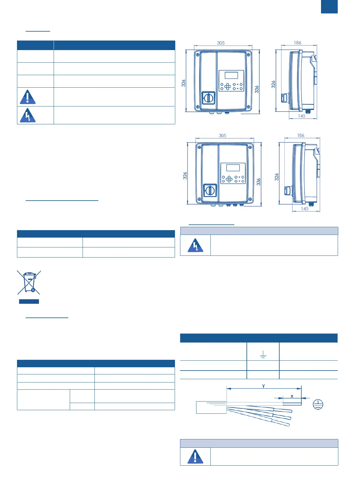
3.4 DIMENSIONS
Sanicubic
Sanifos
4. INSTALLATION
DANGER
Submersion of the control device.
Risk of electric shock!
Only use the control device in rooms safe from floods.
4.1 WALL MOUNTING
The Smart controm box must be installed indoors, in a place protected
from humidity and frost.
The Smart control box is supplied with a wall bracket.
• Mount the wall bracket horizontally, using the appropriate xings for
your wall.
• Snap the Smart control box onto the bracket.
4.2 CONNECTION OF THE FLOAT (SANIFOS) AND PUMP
CABLES
Cables are connected via waterproof terminal blocks.
4.2.1 Preparation of the conductive wires
Connector
Conductor PE 1~: N, L
3~: L1, L2, L3
Disassembly length y (mm) 33 25
Stripping length x (mm) 8 8
4.2.2 Connectors wiring for pumps (Sanipump)
NOTICE
It is imperative to respect the colours of the wires
when making the connections so as not to cause a mal-
function.
 Loading...