EN
19
4.2.5 Connection to the Smart Control Box
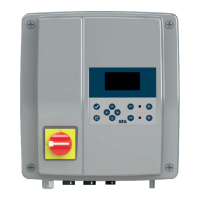
4.2.5.1 Connecting and locking the connector
1
4.2.5.2 Unlocking and disconnecting the connector
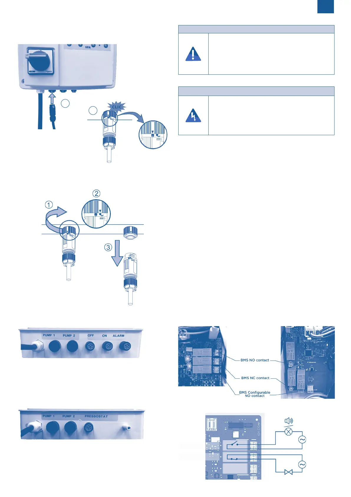
4.2.5.3 Location of Connector Connections
Sanifos
Pump 1: Pump 1
Pump 2: Pump 2
OFF: Low level oat
ON: High level oat
ALARM: Alarm oat
Sanicubic
Pump 1: Pump 1
Pump 2: Pump 2
PRESSOSTAT: ON/Alarm level
NOTICE
Pulling force on the cables.
Risk of tearing.
Cut the cables to the correct length.
Strip cables and wires.
Never pull or move the cables when they are connected.
Do not exert any constraints, e.g. by bending the
cable too tightly.
4.3 ELECTRICAL CONNECTION
DANGER
Electrical connection work performed by an unqua-
lied personnel.
Risk of electric shock!
The electrical connection must be carried out by a
qualied electrician.
The electrical connection must comply with the stan-
dards in force in the country of installation.
The device’s power supply must be connected to ground (class I) and
protected by a high sensitivity dierential circuit breaker (30 mA) rat-
ed at:
- 25 A for single-phase Sanicubic 2 VX, Sanifos with 2 single-phase
Sanipump SLD,
- 16 A for all other cases.
The connection must be used exclusively to provide the power to the
Smart Control Box.
4.4 CONNECTING THE WIRED EXTERNAL ALARM BOX
The cable from the external alarm box is already connected to the elec-
tronic board.
• Connect the jack to the bottom of the external alarm box.
Note: The power supply of the external alarm box is done through the
Smart box. If the jack plug is incorrectly inserted, the external alarm
box will signal a power failure (see
6.4.4 Operation).
4.5 CONNECTION TO THE BMS
Option of a remote alarm facility : dry contact (no voltage).
3 BMS are available: a BMS with NO (Normally Opened) contact, a BMS
with NC (Normally Closed) contact and a congurable NO BMS (see
6.3.3SettingsMenu
).
This contact opens (Normally Closed contact)/closes (Normally
Opened contact) as soon as the station is in alarm mode and remains
opened/closed as long as the default has not been corrected.
The terminals can be connected to a BMS (Building Management Sys-
tem) system or to a live system (max. AC 250V / 16A, DC 250V / 17A).
• Use one of the pre-holes on the side of the enclosure.
• Open the hole by tapping rmly with a screwdriver.
• Connect the connection cable directly to the circuit board using the
illustrations below:
Location of BMS
Single-phase version: Three-phase version:
Wiring diagrams
Single-phase version:
NO dry contact
NC dry contact
External alarm
2
 Loading...