High-Power Stereo Class-D Audio Power Amplifier
SGM4703 with Adjustable Power Limit and Automatic Level Control
19
DECEMBER 2022
SG Micro Corp
www.sg-micro.com
APPLICATION INFORMATION (continued)
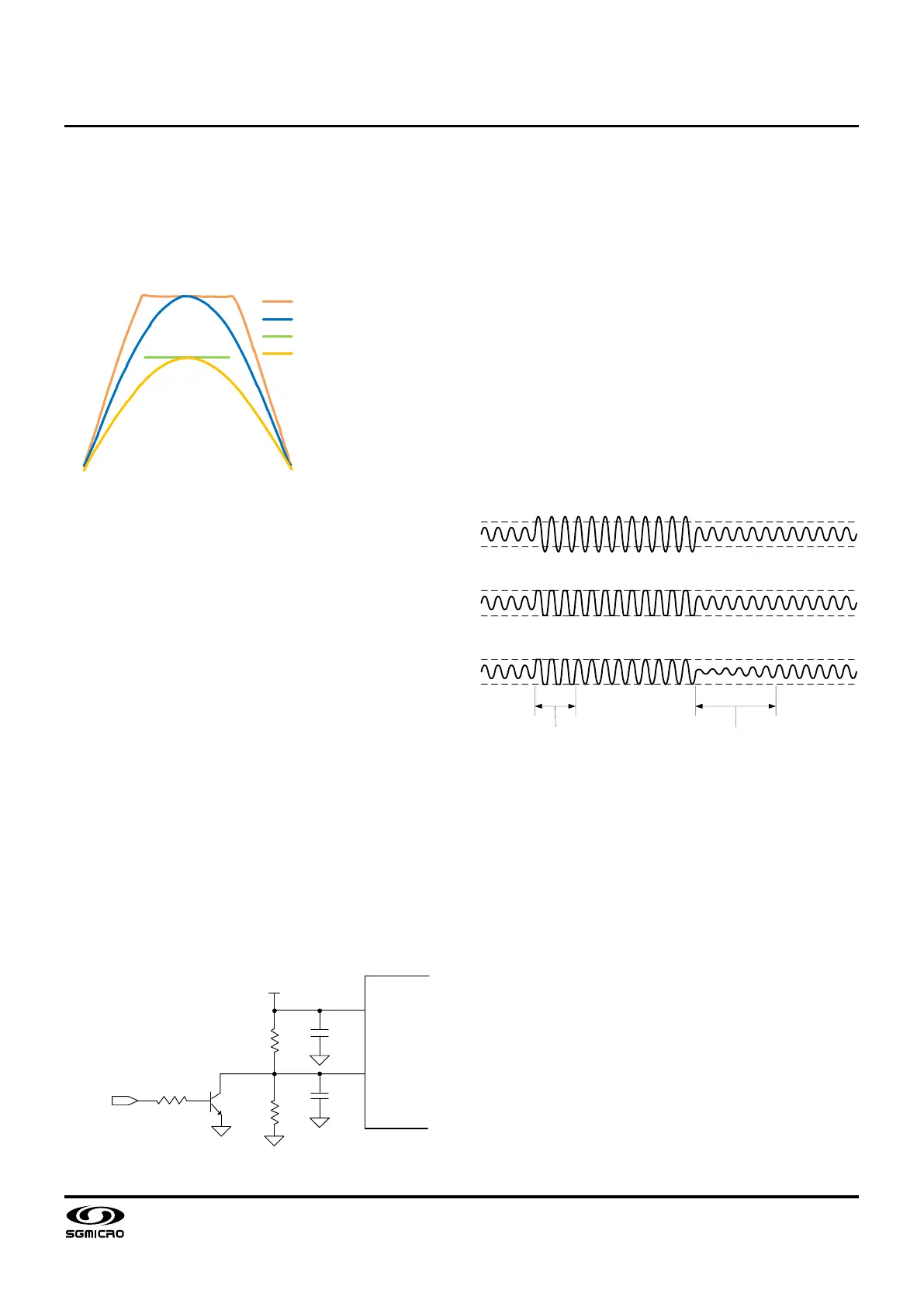
Figure 4 depicts large audio outputs in different
operating modes when excessive inputs are applied to
cause peak outputs higher than either the supply
voltage or a user-defined voltage limit lower than the
supply voltage.
Traditional (No APL No ALC)
ALC with VDD Limiting
APL Output Limiting Voltage
APL with Adjustable Limiting
Figure 4. Large Audio Outputs in Different Operating
Modes
GVDD Supply
The GVDD is an internally generated supply voltage for
internal circuitry. It is also used as the supply voltage for
the resistor divider to set the voltage at the PLIMIT pin.
It is highly suggested to decouple the GVDD pin with a
1μF ceramic capacitor to ground for stable operation.
Note that the current drawn from the GVDD pin by
external circuitry, including all the resistor dividers at
ALC, GAIN, FREQ, and PLIMIT pins, must be kept less
than 5mA.
MUTE Control
The SGM4703 can be configured into mute mode when
the PLIMIT pin is pulled low by an inverting transistor,
as shown in Figure 5. In mute mode, the output stages
of both audio amplifiers are in Hi-Z and the differential
audio outputs (VOPL/R and VONL/R) are pulled to
ground through on-chip resistors respectively. To
restore to its normal operation, the output of the
inverting transistor is reverted to Hi-Z state, allowing
the resistor divider (from GVDD to ground) tapped at
the PLIMIT pin to set the voltage limit for APL.
R
2
R
1
C
PLIMIT
0.1μF
C
GVDD
1μF
Mute
10kΩ
NPN
GVDD
PLIMIT
GVDD
Figure 5. Example Circuit Diagram of Mute Control
Automatic Level Control (ALC)
The automatic level control is to maintain the audio
outputs for a maximum voltage swing without clip
distortion when excessive inputs that may cause output
clipping are applied. With ALC, the SGM4703 lowers
the voltage gain of both audio amplifiers to an
appropriate value such that output clipping is
substantially eliminated.
In Figure 6, “Attack” is the duration where the voltage
gain of the audio amplifiers decreases until output
clipping is substantially eliminated. “Release” is the
duration where the voltage gain of the audio amplifiers
recovers (increases) until it reaches to a value that is
maximally allowed without output clipping.
Attack
Release
Output Signal when Supply Voltage is Sufficiently Large
Output Signal in ALC Off Mode
Output Signal in ALC On Mode
Figure 6. Automatic Level Control Diagram
ALC Mode Select
The SGM4703 can be configured into ALC or Non-ALC
mode via the ALC pin, as described in Table 2. When
the ALC pin is left unconnected, the SGM4703
operates in Non-ALC mode. The Non-ALC mode is
typically chosen for applications where maximum audio
loudness is desired and the amount of output clipping
distortions can be measurably controlled at the audio
source. In other pin configurations, the SGM4703
operates in ALC mode with three specific audio
dynamic characteristics. For most applications, the ALC
mode is preferred for its capability to substantially
eliminate output clipping distortion, excessive power
dissipation and speaker over-load.
 Loading...