High-Power Stereo Class-D Audio Power Amplifier
SGM4703 with Adjustable Power Limit and Automatic Level Control
20
DECEMBER 2022
SG Micro Corp
www.sg-micro.com
APPLICATION INFORMATION (continued)
Three sets of ALC dynamic characteristics can be
selected for specific sound effects, as described in
Table 2. The ALC-1 mode (the ALC pin shorted to GND)
plays music in a most mellow manner with negligible
amount of clipping distortion and lower average output
power. On the other hand, the ALC-3 mode (the ALC
pin shorted to GND via a 300kΩ resistor) plays music in
a most dynamic manner with some extent of clipping
distortion and higher average output power (loudness).
Table 2. ALC Mode Select
ALC Pin
Configuration
ALC
Mode
Sound Effects
Loudness
Clipping
Open Non-ALC
Potentially highest
loudness
No control on
output clipping
Shorted to GND ALC-1
(Lowest loudness
Negligible
output clipping
68kΩ to GND ALC-2 Medium loudness
300kΩ to GND ALC-3
(Highest loudness
Acceptable
output clipping
Note: The resistor tolerance of R
ALC
should be 5% or better.
Voltage Gain Setting
To accommodate various application requirements, the
SGM4703 features 4 selectable voltage gains for audio
amplifiers. An external resistor R
GAIN
from the GAIN pin
to ground sets the voltage gain, as shown in Table 3.
Although the voltage gains as described in Table 3 vary
a little (less than 2%) from parts to parts, the input
impedances at the same voltage gain may vary by ±20%
over parts, due to process variations in the actual
resistance of the input resistors. For design purposes,
the input impedance should be assumed to be 10kΩ,
which is the absolute minimum input impedance of the
audio amplifiers in SGM4703. At lower gain settings,
the input impedance could be as high as 60kΩ.
Table 3. Voltage Gain Select
INI
V
V
Open 30 20 26
Shorted to GND 20 30 30
68kΩ to GND 12 50 34
300kΩ to GND 60 10 20
Note: The resistor tolerance of R
GAIN
should be 5% or better.
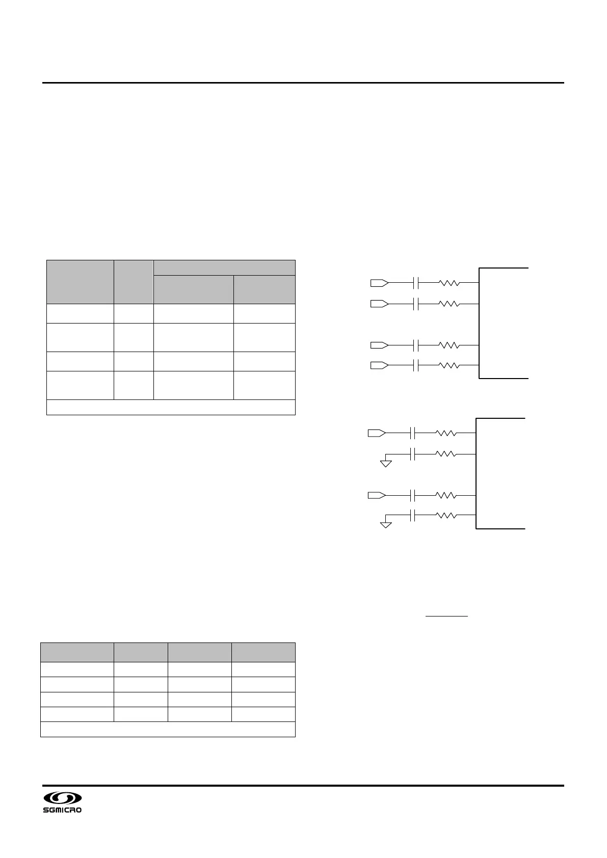
The voltage gain of the audio amplifiers can be slightly
adjusted by inserting small external input resistors R
INE
,
in series with the input capacitors C
IN
, as depicted in
Figure 7 and Figure 8 for differential and single-ended
inputs respectively. In the figures, it is required that C
IN
= C
INL1/2
= C
INR1/2
and R
INE
= R
INL1/2
= R
INR1/2
.
As depicted in Figure 8, the unused inputs of SGM4703
in single-ended inputs applications must be
AC-grounded at the audio source. Also, take care to
match the impedances of two differential inputs.
INPL
INNL
INNR
INPR
R
INL1
C
INL1
R
INL2
C
INL2
C
INR1
C
INR2
R
INR1
R
INR2
INPL
INNL
INNR
INPR
Figure 7. Gain Setting (Differential Inputs)
INPL
INNL
INNR
INPR
R
INL1
C
INL1
R
INL2
C
INL2
C
INR1
C
INR2
R
INR1
R
INR2
INL
INR
Figure 8. Gain Setting (Single-Ended Inputs)
The value of R
INE
(in kΩ) for a given voltage gain can be
calculated by Equation 1, where A
V
is the voltage gain
of the audio amplifier.
(1)
The choice of the voltage gain will strongly influence
the loudness and quality of audio sounds. In general,
the higher the voltage gain is, the louder the sound is
perceived. However an excessive voltage gain may
cause audio outputs to be severely clipped (Non-ALC
mode) or compressed (ALC mode) for high-level (loud)
audio sounds. On the other hand, an unusually low gain
may cause relatively low-level (quite) sounds soft or
inaudible. Thus it is crucial to choose a proper voltage
gain for well balanced audio quality.
 Loading...