PAGE 17
PAGE 16
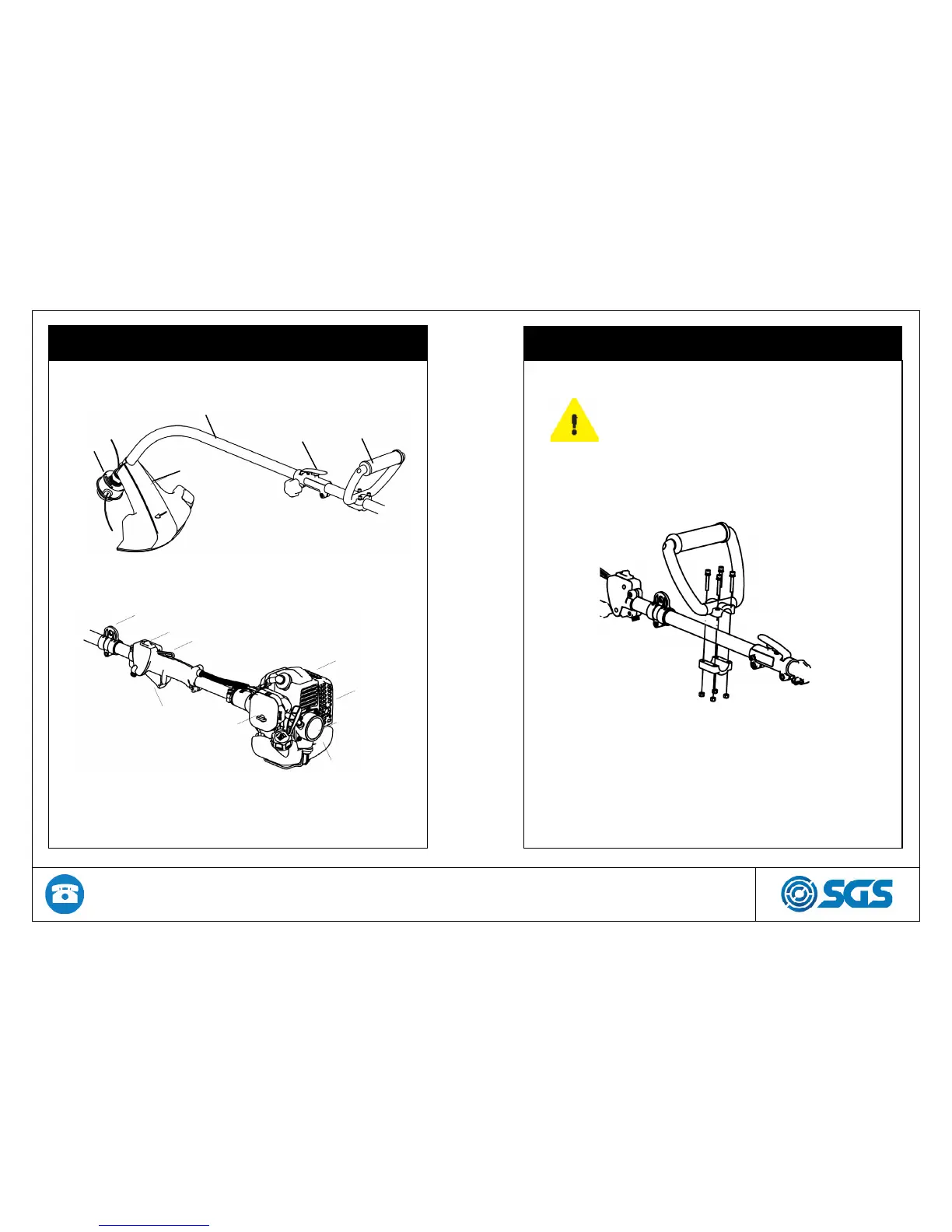
2. COMPONENTS LOCATION DIAGRAM
Trimmer
head
Cutting
attachment
guard
Shaft
Split shaft
connector
Loop
handle
Harness
suspension
point
On/off
switch
Throttle control
Throttle
trigger
Air filter
Engine
Muffler
Fuel
tank
Starter
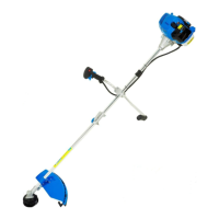
3. ASSEMBLY ENTS LOCATION DIAGRAM
Fitting the loop handle
• Position the handle on the shaft.
• Secure the loop handle with bolts and nuts
provided in the tool kit.
Make sure unit is assembled correctly as shown
in this manual. Be sure to follow all the assembly
instructions.