The connecting rod is made of 35CrMoA. There is coupling mark on the body and cap. You
must install according to the mark; wrong installing should be avoided. The tightening torque
of the connecting rod bolts is50 – 60N.m.
The connecting rod bearing is made of steel back alloy with aluminum, tin, silicon and
cuprum.
While mounting the piston pin, the piston should be heated to 100°C, while mounting the
connecting rod, the piston top face to the installer, the tub concave is on the upper side, and the
bearing positioning slot in the connecting rod big end hole should also be on the lower side.
The weight of connecting rod big end & small end has a strict distribution portion; the weight
difference of piston and connecting rod assembly of each engine should be limited to below 20g.
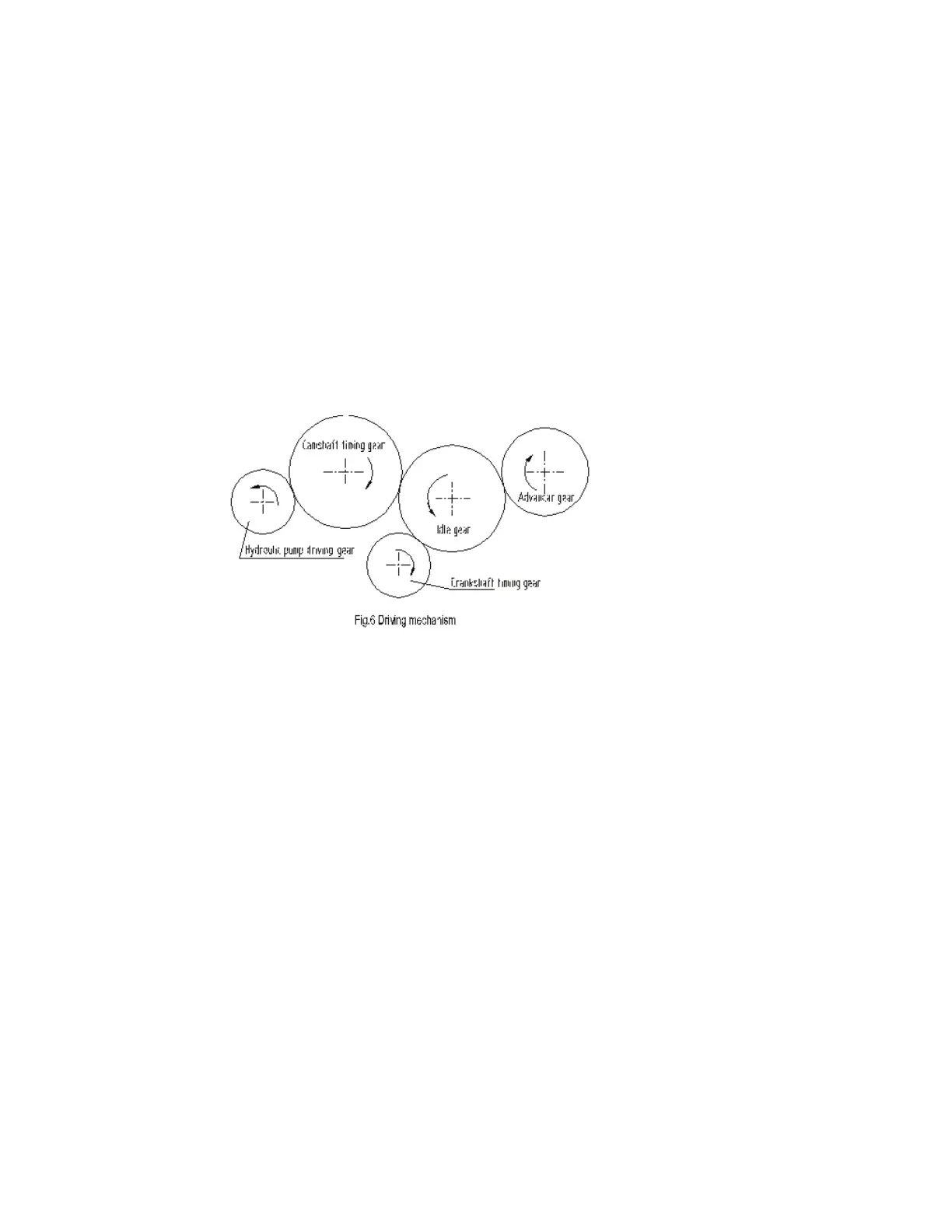
5. DRIVING MECHANISM
The gear driving system of the engine, please refer to Fig.6.
When installing the gears, pay attention to the timing mark on the gear faces to ensure good
phasing and fuel delivery.
After installing the idle gear, check axial clearance. Each gear should turn easily without
clicking.
6 . V AL V E SY ST EM
V a lv e mec ha ni s m:
The mechanism is top - mounted valve type. The camshaft is made of No. 45 steel choicely. The
surfaces of camshaft and gear are high frequency quenched. There is a thrust plate in front of first
shaft journal. Axial clearance of camshaft is 0.07-0.245 mm.
Valve tappet is made of chilled casting iron. There is a position deviation between tappets
center and cam center, so that the tappet could continuously turn for smooth wearing during
operation to prevent seizing. Push rod is made of steel; one end is bail structure, the other end is of
bowl structure. Rocker arm shaft is fully supported for high rigidity. Rocker arm and shaft are
lubricated by pressed oil from cylinder head.
Valve and valve seat are made of alloy steel and alloy cast iron and lapped to fit. To check its
fitting, pour kerosene into air port and wait for 2 minutes, no leakage is allowed. Air leakage of
the valve may affect engine technical performance or even burn to damage valve and seat. So
leakage check should be carried out according to technical requirement when in operation. Lap it
when necessary.
A chamfer is designed on valve guide to prevent oil flowing back into cylinder liner and
burning.
 Loading...