Do you have a question about the Shark 200 and is the answer not in the manual?
Mounting the meter using ANSI studs, noting torque specifications.
Mounting the meter using DIN mounting brackets.
Wiring diagram for a 3-phase, 4-wire WYE direct connection.
Wiring diagram for a 3-phase, 4-wire WYE connection with PTs.
Wiring diagram for a 3-phase, 3-wire Delta direct connection.
Wiring diagram for a 3-phase, 3-wire Delta connection with PTs.
Steps to enter the meter's configuration menu using faceplate buttons.
Configuring CT numerator, denominator, and scaling settings.
Configuring PT numerator, denominator, and scaling settings.
Configuring connection type, meter address, baud rate, and communication protocol.
Configuring display scrolling and saving meter settings.
Examples of CT numerator and scaling values for different amp ratings.
Examples of PT numerator, denominator, and scaling values for different voltage ratings.
Steps to connect the meter to a PC using CommunicatorPQA software via RS485.
Navigating Device Profile screens to view and configure meter settings.
Detailed configuration of CT and PT numerator, denominator, and multiplier settings.
Configuring COM ports, address, protocol, and baud rate for communication.
Instructions for setting the internal clock of the meter.
Assigning a unique designation to the meter for log database identification.
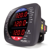
The Shark® 200 Meter is a power and energy meter designed for various electrical monitoring applications. It is crucial that installation is performed by qualified personnel adhering to standard safety precautions, as dangerous voltages and currents can be present in many parts of the unit during normal operation, including terminals, connected CTs (Current Transformers), PTs (Potential Transformers), and I/O modules. Appropriate safety gear such as gloves, glasses, and protective clothing are strongly recommended. The meter should not be used for primary protection or in an energy-limiting capacity, but rather as secondary protection. Users should consult the meter's Installation and Operation Manual for additional safety warnings and detailed instructions.
The Shark® 200 Meter provides comprehensive power and energy monitoring capabilities. It can be configured for various wiring schemes, including WYE direct (3-phase, 4-wire), WYE with PTs (3-phase, 4-wire), Delta direct (3-phase, 3-wire), and Delta with PTs (3-phase, 3-wire). The meter allows for the programming of CT and PT ratios, communication settings, and time synchronization. It supports communication via an RS485 port and can be managed using Electro Industries/GaugeTech's CommunicatorPQA™ software. This software enables users to connect to the meter, configure its settings, and retrieve data. The meter is designed to measure and record electrical parameters, making it suitable for revenue metering, power quality analysis, and energy management.
| Brand | Shark |
|---|---|
| Model | 200 |
| Category | Measuring Instruments |
| Language | English |