Do you have a question about the Shark 100 and is the answer not in the manual?
Details different configurations for three-phase power, focusing on Wye and Delta connections.
Explains the Wye connection, its Y-like appearance, grounding, and common voltage levels.
Describes Delta connections, how windings are arranged, and variations in grounding and wire count.
Explains Blondel's Theorem and its role in simplifying three-phase power measurement methods.
Differentiates between power, energy (kWh), and demand, crucial for billing and analysis.
Discusses reactive power and power factor, essential for understanding total power flow and system efficiency.
Explains harmonic distortion, its causes from non-linear loads, and its impact on waveform quality.
Defines power quality and outlines common problems, their causes, and potential sources.
Details the physical design, advanced measurement capabilities, and connectivity options of the meters.
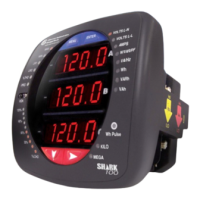
Describes the Shark® 100 meter/digital transducer, its features like IrDA, RS485/RJ45 ports, and mounting options.
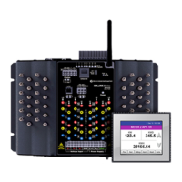
Focuses on the Shark® 100T transducer, its communication protocols, and DIN rail mounting.
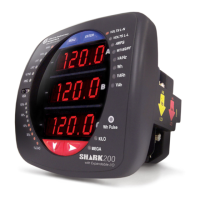
Details the Shark® 100B meter, emphasizing BACnet IP, Web interface, and integration with building systems.
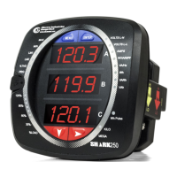
Outlines the Shark® 50 meter's functionality, accuracy, and basic features, differentiating it from the Shark® 100.
Explains the specifications for universal voltage inputs and the dual input method for current measurements.
Provides ordering information and options for Shark® 100/100T models.
Explains V-Switch™ Technology for enabling meter features via communication and upgrades.
Lists all measurable values available in real-time, average, maximum, and minimum modes.
Describes the meter's capability for user-configured Block and Rolling Window Demand for utility applications.
Details the meter's electrical specifications, including power supply and voltage input parameters.
Lists the relevant industry standards and certifications the meter adheres to for safety and performance.
Presents detailed accuracy specifications for various measurements for the Shark® 100 models.
Introduces the installation process, mentioning ANSI/DIN mounting and tool requirements.
Provides detailed steps for installing the meter using the standard ANSI mounting method.
Outlines the procedure for installing the meter using the DIN mounting standard, including bracket usage.
Explains the specific DIN rail mounting procedure for the Shark® 100T transducer.
Emphasizes critical safety precautions, personnel qualifications, and potential hazards during meter installation.
Details the common method for terminating CT leads directly onto the meter's current gills.
Explains passing CT wires through the meter without termination, suitable for specific wiring setups.
Describes using quick connect crimp-on connectors for efficient termination, especially for portable applications.
Guides on connecting voltage inputs and the power supply to the meter using the appropriate connectors.
Specifies the requirement to connect the meter's ground terminals to the installation's protective earth ground.
Recommends using fuses on voltage inputs and the power supply for electrical protection.
Provides visual guides for various electrical connection configurations for the meters.
Describes the EI-MSB10-400 surge protector for substation instrumentation applications.
Details the RS485/KYZ output option, including standard port settings and its use for energy pulsing.
Explains the use of the Unicom 2500 converter for RS485 to RS232 communication with a PC.
Guides on setting up the Shark® 100 meter for Ethernet communication via a LAN using Telnet.
Details the steps for configuring the host PC's Ethernet adapter for communication with the meter.
Outlines the factory default Ethernet settings and procedures for configuring the meter via Ethernet.
Instructions for establishing a Telnet connection to configure the meter's Ethernet settings from the PC.
Explains how to reset the Ethernet card to its factory default settings using the reset button.
Refers to Chapter 7 for detailed instructions on configuring the Shark® 100B meter's Ethernet communication.
Details how to program the meter using its front panel buttons and interactive elements.
Describes the various indicators and displays on the meter's faceplate, such as reading type and parameter designators.
Explains the functionality of the Menu, Enter, Down, and Right buttons for navigating the meter interface.
Covers accessing and navigating through the meter's different operational modes via the front panel.
Details the initial startup sequence and the default displays shown by the meter upon power-up.
Guides on accessing and navigating the meter's main menu to select various operational modes like Reset or Configuration.
Provides instructions for performing a meter reset, including password entry if security is enabled.
Explains the process of entering a password for accessing protected functions like reset or configuration.
Details how to access and navigate the configuration mode to adjust various meter settings.
Explains how to enable or disable the auto-scrolling feature for meter parameters displayed on the screen.
Guides on setting the CT numerator, multiplier, and denominator for accurate current measurements.
Provides instructions for configuring the PT numerator, multiplier, and denominator for accurate voltage measurements.
Details how to select and configure the appropriate connection type (Wye or Delta) for the meter's wiring.
Guides on setting communication parameters like address, baud rate, and protocol for ports.
Describes how to use the meter's default operating mode to view various electrical parameters and readings.
Explains the functionality of the % of Load Bar, a 10-segment LED graph representing current load.
Details the process for verifying the meter's energy measurement accuracy using test pulses.
Explains how to program the meter or transducer using external software via communication.
Describes accessing the meter in default RS485 mode for debugging or retrieving settings.
Provides instructions for establishing a connection to the meter using the Communicator EXT™ software.
Guides on configuring device profile settings, including CT/PT ratios, system wiring, and phase display settings.
Introduces the Shark® 100B meter's native BACnet/IP capabilities and its Web interface for configuration.
Explains the BACnet protocol, its development, and how it uses Objects and Properties for data communication.
Lists the predefined BACnet objects available for electrical measurements on the Shark® 100B meter.
Details the network configuration steps needed to establish communication with the Shark® 100B meter.
Guides on utilizing the meter's Web interface for parameter changes, data viewing, and downloading.
Introduces the navigation maps, explaining their purpose in illustrating meter operation and programming.
Presents a series of navigation maps showing detailed screen flows for different meter modes.
Illustrates the navigation flow within the meter's main menu, including button functions and mode selection.
Details the navigation paths for accessing and viewing various operating mode screens on the meter.
Shows the sequence of screens involved in performing a meter reset, including password prompts.
Maps out the navigation process for entering and modifying meter configuration settings.
Introduces the Modbus maps, explaining their role in detailing meter readings and programming capabilities.
Outlines the structure of the Modbus register map, dividing it into sections like Fixed Data and Meter Data.
Explains various data formats used in Modbus communication, including ASCII, SINT16, SINT32, and FLOAT.
Details the representation and interpretation of 32-bit IEEE floating-point values within the Modbus map.
Refers to the detailed Modbus register maps for Shark® 100 and 50 meters.
Introduces the DNP map and its purpose in showing the meter's application of the DNP Protocol.
Presents the DNP point map, detailing object types like Binary Outputs, Counters, and Analog Inputs.
Details the physical layer implementation of DNP 3.0, emphasizing RS485 communication and network parameters.
Covers considerations for the Data Link Layer, including control fields, function codes, and addressing.
Explains the Transport Layer, noting limitations on multiple-frame messages and frame indicators.
Details the Application Layer, covering headers, control fields, function codes, and application data structure.
Lists the specific Objects and Variations supported by Shark® 100 meters for DNP 3.0 communication.
Explains the Binary Output Status object, used for energy reset and protocol state changes.
Details the Control Relay Output Block object for energy reset and protocol change operations.
Covers the 32-Bit Binary Counter object, used for communicating hour readings.
Explains the 16-Bit Analog Input object for various meter readings like voltage, current, and power.
Describes Class 0 Data, which groups analog inputs, counters, and binary outputs for efficient retrieval.
Covers Internal Indications, including the Device Restart bit that flags meter resets.
Introduces the USB to IrDA Adapter CAB6490 for connecting to the meter's IrDA port.
Details the step-by-step process for installing the USB to IrDA Adapter and its driver software on a PC.
| Brand | Shark |
|---|---|
| Model | 100 |
| Category | Measuring Instruments |
| Language | English |