10
H-VCO, VIF-VCO & S-TRAP fo ADJUSTMENT
NO
ADJUSTMENT POINT
ADJUSTMENT CONDITION / PROCEDURE WAVEFORM OR OTHERS
1 H-VCO ADJ
(Manual Adj)
(I2C BUS CONTROL) (1) In No signal (RASTER) condition.
(AUTO & MANUAL ADJ)
(2) Go to service mode, choose service data
V03
.
(3) Connect oscilloscope to
IC801 pin13 (H-OUT)
, adj
V03
until freq
become
15.625 ± 0.15 KHz.
(Auto Adj)
(1) In No signal (RASTER) condition.
(2) Go to service mode.
(3) Choose service data
V03
, by pressing R/C
Auto (Hex C1)
key, OSD will appear "OK"
at screen.
(4) If appear "NG" pls repeat step 3.
2 VIF-VCO ADJ
(Manual Adj)
*NOTE:
(I2C BUS CONTROL) (1) In No signal (RASTER) condition.
This adjustment must be done after aging
(2) Go to service mode, choose service data
V02.
at least 3 minutes.
(3) Connect oscilloscope to
IC801 pin7 (AFT)
, adj
V02
until voltage become
2.5 ± 1 V.
(Auto Adj)
(1) In No signal (RASTER) condition.
(2) Go to service mode, choose service data
V02.
(3) Press the R/C
Auto (Hex C1)
key, OSD will appear "OK" at screen.
(4) If appear "NG" pls repeat step 3.
3 S-TRAP fo ADJ
(I2C BUS CONTROL) (1) In No signal (RASTER) condition.
(AUTO & MANUAL ADJ)
(2) Go to service mode, choose service data
V20.
(3) Connect oscilloscope to
TP 801
, adj
V20
until voltage become
Min
(below 5 V).
(4) After that pls adj service data
V19& V23 same as "V20", V21 to "V20+ 1", V22 to "V20-2".
(1) In No signal (RASTER) condition.
(2) Go to service mode, choose service data
V20 (S-TRAP I).
(3) Press the R/C
Auto (Hex C1)
key, OSD will appear "OK" at screen.
(4) If appear "NG" pls repeat step 3.
HORIZONTAL ,VERTICAL,DEFLECTION LOOP ADJUSTMENT (1)
NO
ADJUSTMENT POINT
ADJUSTMENT CONDITION / PROCEDURE WAVEFORM OR OTHERS
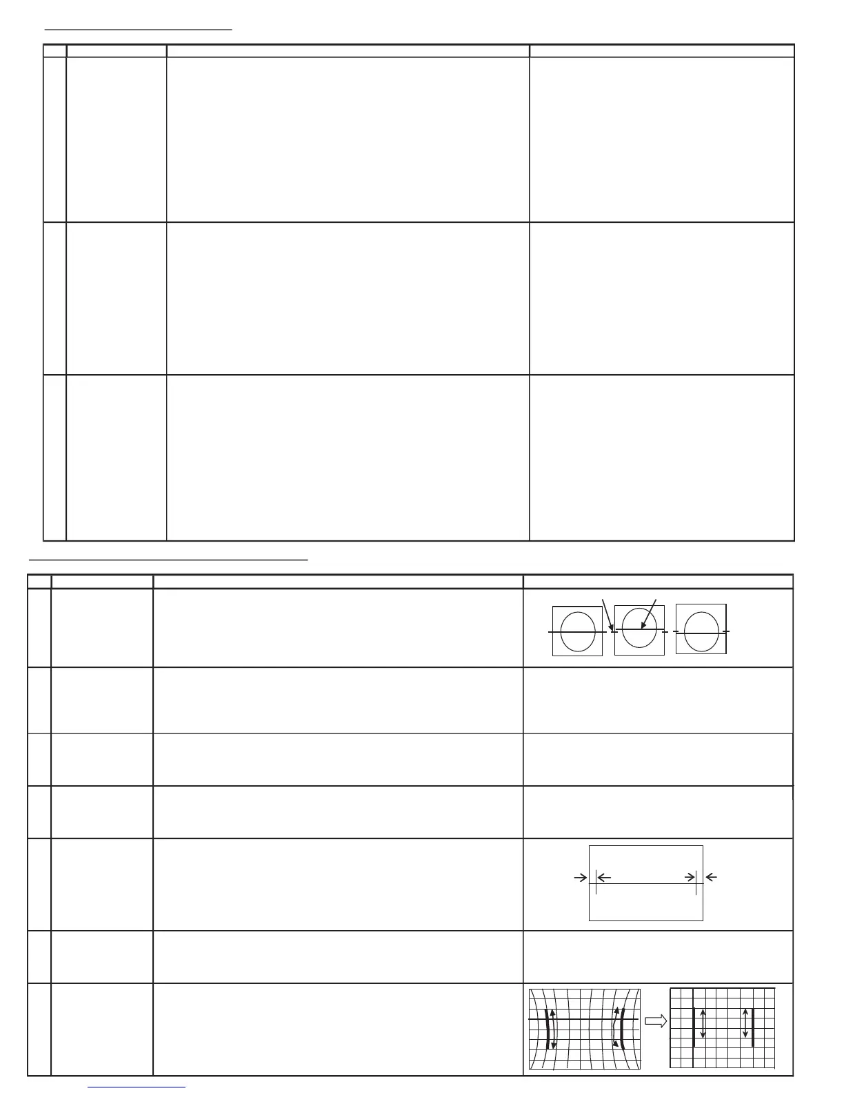
1 V-SHIFT (1) Receive Monoscope Pattern Signal (PAL 50 Hz). Figure A B
(I2C BUS CONTROL)
(2) Choose the service data
V12
.
(3) Adjust
V12
to align the center of the screen to the geometric center of CRT.
Note: B line (Monoscope middle line) must same or nearest higher position
to the A mark (Tube middle mark),refer to the attach drawing.
OK OK NG
2 V-SIZE (1) Receive Monoscope Pattern Signal (PAL 50 Hz).
(I2C BUS CONTROL)
(2) Choose the service data
V11
.
(to be done after V-shift adj)
(3) Adjust
V11
bus data until the overscan become
10 ± 1.5 %.
Caution 1: Pls aging TV more than 10 minutes before adjustment
3 V-LINEARITY (1) Receive Monoscope Pattern Signal (PAL 50 Hz).
(I2C BUS CONTROL)
(2) Choose the service data
V29
.
(3 )Already preset. (Adjust this unless the linearity is not achieved.)
4 VS CORRECTION (1) Receive Monoscope Pattern Signal (PAL 50 Hz).
(I2C BUS CONTROL)
(2) Choose the service data
V27
.
(3 )Already preset. (Adjust this unless the linearity is not achieved.)
5 H-SHIFT (1) Receive Monoscope Pattern Signal (PAL 50 Hz).
(I2C BUS CONTROL)
(2) Choose the service data
V13
.
(3) Adjust the
V13
bus data to have a balance position to spec of
A=B
(as attach drawing).
A B
(4) If cannot make it to
A=B
, adjust from the best point so that
A
slightly smaller than
B
.
6 H-SIZE (1) Receive Monoscope Pattern Signal (PAL 50 Hz).
(I2C BUS CONTROL)
(2) Choose the service data
V36
(3) Adjust
V36
bus data until the overscan becomes
10 ± 1.5 %.
7 PARABOLA (1) Receive CrossHatch Pattern Signal (PAL 50Hz).
(I2C BUS CONTROL)
(2) Choose the service data
V32
Adjust the 2nd vertical line from the right end of the crosshatch pattern
so that the middle 4 blocks are straight.
(3) Make sure both left / right of 2nd vertical line at optimum point