21G-FX10L
5 – 6
PIF A
DJUSTMEN
T
CHECKING
NO
ADJUS
TMENT POIN
T
ADJUSTMENT CONDIT
ION/PROCEDU
R
E
WAVEFORM OR OTHERS
1
RF-AGC
(1) Recei
ve the "US 10 CH HALF Color B
ar" signal
.
*
for Auto ADJ
T
A
KE OVE
R
P
OINT
Signal
Strength: 56 ± 1dBμV (75 ohm open)
1)Receive "NTSC C
O
L
O
UR BAR"
sig
nal
AD
J
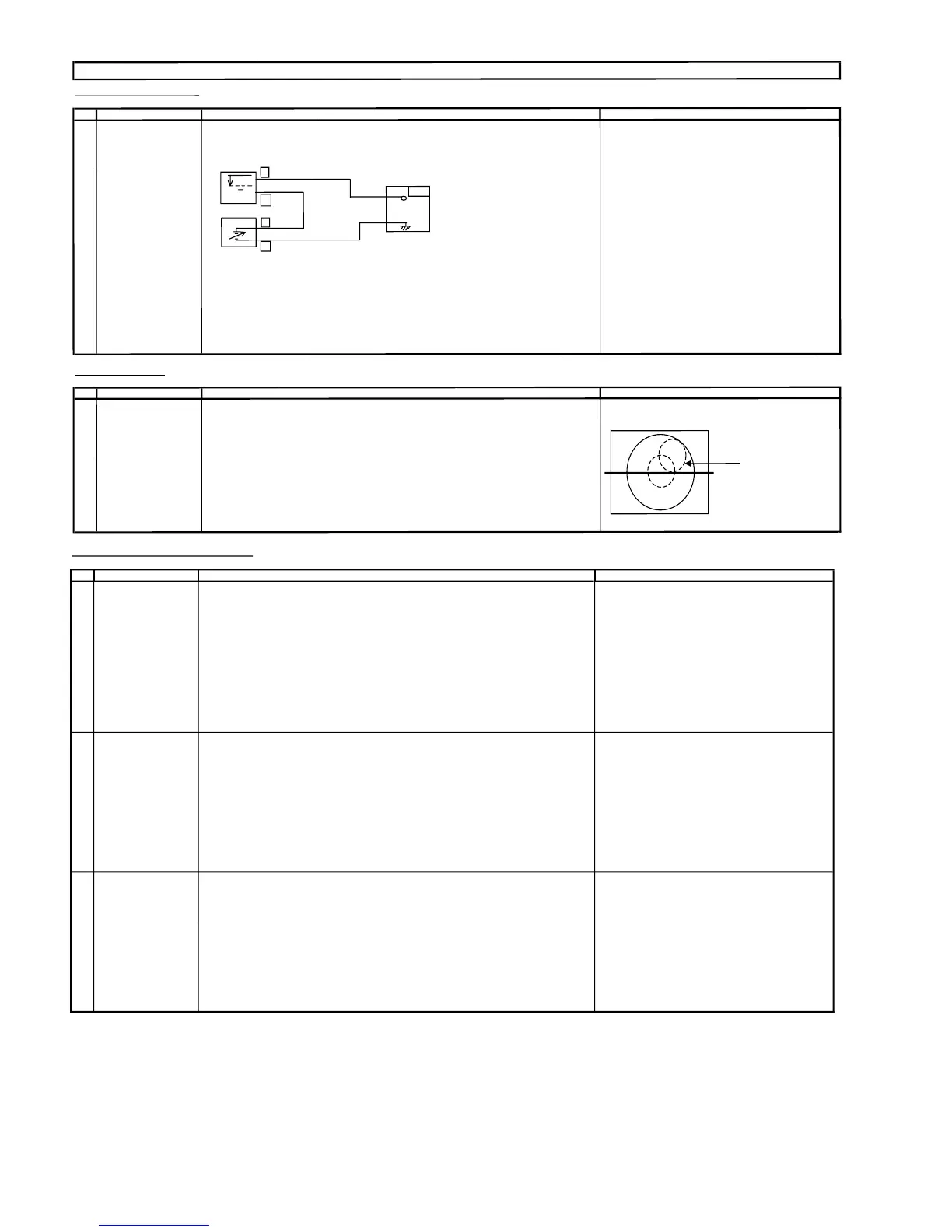
USTMENT (2) Connect t
he oscillos
cop
e
t
oJA402(Tuner's AGC Terminal) as shown in
s
i
gnal strength :56±1dBμV(75ohmo
p
en).
(I2C BUS CONTROL) figure 3-1
.
1) Go to s
ervice mode.
OSCILLO
SCOPE
2) Go
to servic
e
data V09 , press R/C to operate
(A
UTO & MANUAL
A
DJ)
"Auto-AGC" key and confirm the OK display
on the screen
3
)Ifappear red display w
i
th NG s
i
gn, inc
rease data some
s
t
ep and pleas
e repeat step 2.
BIAS BOX
4) Proceedstep4&5in
manual
mode
.
T
V
SET
Bias Box : about 4.5V
Fig. 3
-1
(3) Call V09 i
nservicemode. Adjust the V09busdatatoobtain theTuner
outputpindrop 0.1V b
elow maximum voltage.
(4) Ch
a
n
ge the antenna inpu
t
signal to 63 ~67dBμV, and makes
u
re the
re
i
s
n
onois
e.
(5)T
u
rn uptheinput s
ignal to 9
0
~95dBμVto be sure that the
re i
s
n
o cross
modulationbeat.
FO
CUS ADJUSTME
N
T
NO ADJ
USTMENT POIN
1 FOCUS (1) Receive
U
S4 CH
L
ION HEAD Signal
(NTSC 60 Hz).
(2) Press RESET to set Picture N
ORMAL condition.
(3) Adjust the focus control to get the bes
t
focusing.
ADJUSTMENT PRECAUTION : M
ake sure TV Set is in "NORMAL CONDITION" b
e
fore switch t
o Service
Mode for Adj
u
stment.
Focusing Point(middle
of ce
n
ter andedgeof
monoscope pattern)
+
-
+
-
JA
402
0.1V
H-VCO, VIF-VCO & S-TRAP fo ADJUSTMENT
NO
ADJUSTMENT POINT
ADJUSTMENT CONDITION / PROCEDURE
WAVEFORM OR OTHERS
1 H-VCO ADJ
(Manual Adj)
(I2C BUS CONTROL)
(1) In No signal (RASTER) condition.
(AUTO & MANUAL ADJ)
(2) Go to service mode, choose service data
V25.
(3) Connect oscilloscope to IC801 pin13 (H-OUT)
,adjV25 until freq
become 15.735 ± 0.2KHz.
(Auto Adj)
(1) In No signal (RASTER) condition.
(2) Go to service mode.
(3) Choose service data V25,bypressingR/C
"AUTO H-VCO" key, OSD will appear "OK"
at screen.
(4) If appear "NG" pls repeat step 3.
2 VIF-VCO ADJ
(Manual Adj)
*NOTE:
(I2C BUS CONTROL)
(1) In No signal (RASTER) condition.
This adjustment must be done after aging
(AUTO & MANUAL ADJ)
(2) Go to service mode, choose service data V14
at least 3 minutes.
(3) Connect oscilloscope to IC801 pin7 (AFT)
, adj V14 until voltage become
2.5 ± 0.5 V DC (Checking spec : 2.50 ± 1.5 V)
(Auto Adj)
(1) In No signal (RASTER) condition.
(2) Go to service mode, choose service data V14.
(3) Press the R/C "AUTO PIF-VCO"
key, OSD will appear "OK" at screen.
(4) If appear "NG" pls repeat step 3.
3
S-TRAP fo ADJ
(Manual ADJ
)
(I2C BUS CONTROL) (1) In No signal (RASTER) condition.
(AUTO & MANUAL ADJ)
(2) Go to service mode, choose service data V26.
(3) Connect oscilloscope to TP 801 or IC801 pin 30
, adj V26 until voltage become Min (below 5 V).
(Auto Adj)
(1) In No signal (RASTER) condition.
(2) Go to service mode, choose service data
V26.
(3) Press the R/C "AUTO S-TRAP" key, OSD will appear "OK" at screen.
(4) If appear "NG" pls repeat step 3.