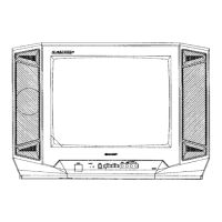
This document is a service manual for the SHARP 28 SYSTEM COLOUR TELEVISION, specifically for models 29A-SX1, 29A-SX5, and 29A-SX8. It provides comprehensive information for qualified service personnel regarding the maintenance, repair, and adjustment of these television sets.
Function Description
The SHARP 28 System Colour Television is designed to display colour video signals across 28 different systems. It features a multi-system compatibility, allowing it to operate in various regions with different broadcasting standards. The television includes a component input terminal (rear) for enhanced video connectivity, a twin buss reflex SP box for improved audio, and a double dynamic picture circuit for optimized image quality. It is CATV ready, indicating compatibility with cable television systems. The integration of a PAL/NTSC digital-comb filter ensures superior picture clarity by reducing cross-colour and dot crawl artifacts. For an immersive audio experience, the television incorporates a sound spatializer and an aperture control circuit for fine-tuning image sharpness.
Specific models offer additional features:
- 29A-SX5/29A-SX8: Include NICAM-I.B/G and IGR-B/G audio decoding for high-quality stereo sound.
- 29A-SX5: Features TEXT functionality with multi-language support (English, German, French, Spanish, Italian, Swedish).
All models utilize a super flat picture tube for a modern aesthetic and reduced screen distortion, along with a CTI SRT circuit for further picture enhancement.
Important Technical Specifications
Power Input and Consumption:
- Power Input: AC 110-240V, 50/60Hz (Auto-switching)
- Power Consumption:
- 29A-SX1: 185W
- 29A-SX5: 195W
- 29A-SX8: 190W
Picture Tube and Deflection:
- Convergence: Self Convergence System
- Focus: Bi-Potential, Uni-Potential Electrostatic
- Sweep Deflection: Magnetic
Intermediate Frequency (IF):
- Picture IF Carrier: 38.9 MHz
- Sound IF Carrier:
- 6.5 MHz: 32.4 MHz
- 6.0 MHz: 32.9 MHz
- 5.5 MHz: 33.4 MHz
- 4.5 MHz: 34.4 MHz
- Colour Sub-Carrier:
- PAL/NTSC: 34.47 MHz
- SECAM: 34.494/34.65 MHz
- NTSC: 35.32 MHz
Audio Output:
- Audio Power Output Rating: 20W x 2 total (40W Max)
- Speaker: 8 x 12 cm x 2pcs, 10cm Round x 2pcs.
- Speaker Box Unit Impedance: 6.2 ohm at 400Hz
Reception:
- Aerial Input Impedance: 75 ohm Unbalanced
- Receiving Channels:
- PAL-B/G, SECAM-B/G:
- VHF: E2 thru E12
- UHF: E21 thru E69
- CATV: X thru Z + 2, S1 thru S41
- PAL-D/K, SECAM-D/K:
- VHF: R1 thru R12, C1 thru C12
- UHF: 21 thru 69, C21 thru C57
- PAL-I, SECAM-I:
- VHF (IRELAND): B thru J
- UHF (U.K., H.K.): 21 thru 69
- NTSC-M:
- VHF (US): 2 thru 13
- VHF (JAPAN): 1 thru 12
- UHF (US): 14 thru 69
- UHF (JAPAN): 13 thru 62
- CATV (US): A-6 thru A-1, A thru W+29
- CATV (JAPAN): C13 thru C63
- Receiving Frequency:
- VHF: 44.25 MHz thru 463.25 MHz (29A-SX1), 45.25 MHz thru 463.25 MHz (29A-SX5/SX8)
- UHF: 471.25 MHz thru 863.25 MHz
Dimensions:
- Width: 800mm
- Height: 579mm
- Depth: 484mm
- Weight (Approx): 43.0kg
Usage Features
The television offers a user-friendly interface with multi-language On-Screen Display (OSD) support, including English, Chinese, Russian, French, Arabic, and Malay. This allows users to navigate menus and settings in their preferred language. The remote control provides access to various functions, including channel selection, volume control, and adjustment of picture and sound settings.
The service mode, accessible by short-circuiting TP1001/1002, allows for detailed adjustments of various parameters, including vertical size, linearity, S-correction, horizontal position, and size. Initial values for these settings are automatically loaded from the E²PROM, ensuring a consistent starting point for adjustments. The television is designed with user safety in mind, featuring integral implosion protection for the picture tube and minimal X-Ray radiation.
Maintenance Features
The service manual emphasizes that maintenance and repair should only be performed by qualified service personnel. Key maintenance features and precautions include:
High Voltage System and Picture Tube Servicing:
- Static Charge Removal: Before servicing the high voltage system, static charge must be removed from the picture tube by connecting a 10k ohm resistor in series with an insulated wire between the picture tube dag and the 2nd anode lead. The AC line cord must be disconnected first.
- Picture Tube Replacement: Only tubes of the same type number should be used for replacement to ensure continued safety.
- Handling Precautions: The picture tube should not be lifted by its neck. Shatterproof goggles must be worn, and the high voltage must be completely discharged before handling the tube.
X-Ray Radiation Precautions:
- The television is designed to minimize X-Ray radiation. However, certain malfunctions or prolonged exposure during servicing can lead to hazardous radiation.
- High Voltage Limit: High voltage should not exceed 33.0 kV (at beam 0µA).
- Normal Operation Voltage: The set should function at 29.5 ± 1.5kV (at beam 1.7 mA). High voltage must be re-checked after any repairs that might cause fluctuations.
- Picture Tube Substitution: Unauthorized picture tubes should not be used, as they may cause excess X-Ray radiation.
Before Returning the Receiver:
- Lead Dress Inspection: All leads must be inspected to ensure they are not pinched and that no hardware is lodged between the chassis and other metal parts.
- Protective Devices Inspection: All protective devices, such as non-metallic control knobs, insulating fishpapers, cabinet backs, adjustment and compartment covers or shields, isolation resistor-capacity networks, and mechanical insulators, must be inspected.
Adjustment Procedures:
The manual details various adjustment procedures, including:
- PIF Check Adjustment: For RF-AGC cut-in adjustment.
- Video Level Adjustment: For video output at the AV-OUT terminal.
- Digital Comb Filter Y Level Adjustment: For Y signal output at TP5400.
- PAL Chroma Adjustment: For sub-colour adjustment using I²C bus control for RF and DVD signals.
- NTSC Chroma Adjustment: For sub-tint adjustment using I²C bus control for RF and DVD signals.
- SECAM Chroma Adjustment: For bell filter fo adjustment and black level R-Y/B-Y adjustment using I²C bus control.
- Sound Level Adjustment: For SUB VOL adjustment.
- SIF (NICAM/IGR) Adjustment: For VCO COIL T2300 adjustment.
- Cut Off, BKGD Adjustment: For CRT cut-off and white balance background using I²C bus data.
- Sub Cont, Sub-Bright Adjustment: For sub-contrast and sub-bright adjustments using I²C bus control for RF and DVD signals.
- Purity Adjustment: For colour purity and peripheral purity.
- Convergence Adjusting Method: For static and dynamic convergence adjustments.
- Horizontal/Vertical Circuit Adjustment: For various parameters like V-AMPLITUDE, V-LINEARITY, V-S CORRECTION, V-RHASE, H-RHASE, H-SIZE, E/W-PARABOLA, V-BIAS, V-JCORRECTION, EW-CORNER, TRAPEZIUM, V-COMPENSATION, and H-COMPENSATION.
- Focus Adjustment: For picture sharpness.
Troubleshooting Tables:
Detailed troubleshooting flowcharts are provided for common issues such as:
- No Vertical Scan
- No Raster
- No Picture
- No Normal Sound
- No Specific Colour
- Colour Produced (but with issues)
Schematic Diagrams and Parts Lists:
The manual includes comprehensive schematic diagrams for the main unit, CRT unit, power unit, NICAM/IGR unit, and TEXT unit, along with solid-state device base diagrams and waveforms. A complete replacement parts list is provided, with safety-critical parts clearly marked, to ensure that only identical components are used for replacements.