1 CONVERGENCE ADJ
(1) Receive the " Crosshatch Pattern" signal.
( To be done after the Xaxis
purity adjustment.) (2) Using the remote controller, call NORMAL mode.
(no need this adjutment for
( Static convergence ) Yaxis
ITC AK MASK CRT type)
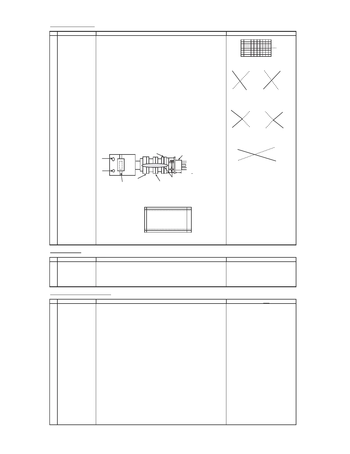
1. Overlap blue and red with the open-/closing angle and rotation of the 4 pole
magnet. BRRB
2. Overlap green on blue and red with the open-/closing angle and rotation of the
6 pole magnet.
( Dynamic convergence )
1. Fix the w edges in a position so that the deflection york neck is at the center of Fig-1
top bottom and left right. ( Straight line and without any blur horizontal / vertical Adjust by VR1
line).
2. Adjust the Red, Blue, upper and lower of the centre y axis on the screen by using
the Volume (VR2, VR1)at the deflection york. B R R B
(Refer to fig.1 and fig.2)
3. If the Horizontal Red, Blue(XV) on the screen centre X axisis shifted, correct the
Red, Blue (XV) by adjusting the balance coil on the deflection york.
(Refer to Fig. 3)
4. After confirm that there is no problems on the entire screen ,bond each wedge on Fig-2
CRT and glass tape on it. Fastening the screws of DY and magnet unit Adjust by VR2
(purity , 4 - pole and 6 pole ), then coat the lacquer paint on DY fastening screw and
magnet unit fastening screw.
VR1
RB
VR2
Fig- 3
Adjust by Balance Coil
Balance Coil
(note)
In case of poor convergence adjustment on the top and bottom and of the screen ,
adjust DY by swing rightward and leftward.
(Refer to Fig-4)
Fig-4
Adjust by Swing DY
1 FOCUS 1. Receive US-12CH Lion Head.
ADJUSTMENT 2. With the remote controller, make the image normal.
3. Adjust the focus VR to make the character"575" on left bottom of monoscope
as fine as possible.
(1) Switch TV to video mode , blue back off , with no video signal
and Press R/C to set picture into normal condition
(2) Go to service mode at adjustment mode item A127 (VG2).
(3) Adjust screen voltage until retrace line appear, the following OSD will appear at bottom of
screen.
UNSTABLE
OUT
ABOVE
(4) Finally , slowly decrease the screen variable resistor until following OSD appear.