EasyManua.ls Logo

Sharp AL-2031

Sharp AL-2031
120 pages
To Next Page IconTo Next Page
Loading...
Parts marked with ā€œ ā€ are important for maintaining the safety of the set. Be sure to replace these parts with
specified ones for maintaining the safety and performance of the set.
This document has been published to be used
for after sales service only.
The contents are subject to change without notice.
SERVICE MANUAL
CONTENTS
SHARP CORPORATION
CODE: 00ZAL2041/S2E
DIGITAL MULTIFUNC-
TIONAL SYSTEM
AL-2021
AL-2031
MODEL AL-2041
AL-2021
AL-2031
AL-2041
[1] GENERAL . . . . . . . . . . . . . . . . . . . . . . . . . . . . . . . . . . . . . . . . . . . 1 - 1
[2] SPECIFICATIONS . . . . . . . . . . . . . . . . . . . . . . . . . . . . . . . . . . . . . 2 - 1
[3] CONSUMABLE PARTS . . . . . . . . . . . . . . . . . . . . . . . . . . . . . . . . . 3 - 1
[4] EXTERNAL VIEWS AND INTERNAL STRUCTURES . . . . . . . . . 4 - 1
[5] UNPACKING AND INSTALLATION . . . . . . . . . . . . . . . . . . . . . . . . 5 - 1
[6] COPY PROCESS . . . . . . . . . . . . . . . . . . . . . . . . . . . . . . . . . . . . . 6 - 1
[7] OPERATIONAL DESCRIPTIONS . . . . . . . . . . . . . . . . . . . . . . . . . 7 - 1
[8] DISASSEMBLY AND ASSEMBLY . . . . . . . . . . . . . . . . . . . . . . . . . 8 - 1
[9] ADJUSTMENTS . . . . . . . . . . . . . . . . . . . . . . . . . . . . . . . . . . . . . . 9 - 1
[10] SIMULATION, TROUBLE CODES . . . . . . . . . . . . . . . . . . . . . . . 10 - 1
[11] USER PROGRAM . . . . . . . . . . . . . . . . . . . . . . . . . . . . . . . . . . . . 11 - 1
[12] CHECKING THE TONER LEVEL . . . . . . . . . . . . . . . . . . . . . . . . 12 - 1
[13] ELECTRICAL SECTION . . . . . . . . . . . . . . . . . . . . . . . . . . . . . . . 13 - 1
[14] CIRCUIT DIAGRAM . . . . . . . . . . . . . . . . . . . . . . . . . . . . . . . . . . 14 - 1

Table of Contents

Question and Answer IconNeed help?

Do you have a question about the Sharp AL-2031 and is the answer not in the manual?

Sharp AL-2031 Specifications

General IconGeneral
Print TechnologyLaser
Print Resolution600 x 600 dpi
Copy Resolution600 x 600 dpi
Scan Resolution600 x 600 dpi
ConnectivityUSB 2.0
Zoom Range (%)25 - 400%
Network Printer (Standard)No
Network Printer (Option)Yes
Network Scanner (Standard)No
Network Scanner (Option)Yes
FunctionsPrint, Copy, Scan
Print Speed20 ppm
Copy Speed20 cpm
Paper Capacity250 sheets
TypeMonochrome Laser
Power Requirements - Rated Local AC Voltage (Hz)220-240 V (50/60 Hz)
Power Consumption (kW)1.2 kW
Supported OS StandardWindows

Summary

[1] GENERAL

Major functions

Overview of the main functionalities and configurations of the multifunctional system.

[2] SPECIFICATIONS

Basic Specifications

Key physical and general specifications of the AL-2021, AL-2031, and AL-2041 models.

Operation specifications

Detailed operational parameters including paper feed, optical, and image forming systems.

[4] EXTERNAL VIEWS AND INTERNAL STRUCTURES

Appearance

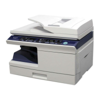
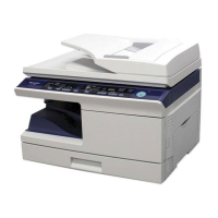
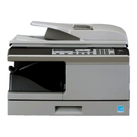
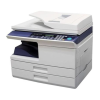
Visual identification of external parts and components of the machine.

Operation panel

Explanation of the control panel layout, keys, indicators, and display functions.

[5] UNPACKING AND INSTALLATION

Copier installation

Instructions and precautions for properly setting up the copier in its operating environment.

Software

Details on the included software and procedures for installing printer and scanner drivers.

[7] OPERATIONAL DESCRIPTIONS

Scanner section

Detailed explanation of the scanner unit, optical system, and drive system components.

Paper feed section and paper transport section

Description of how paper is fed and transported through the machine's various sections.

[8] DISASSEMBLY AND ASSEMBLY

High voltage section

Step-by-step procedures for disassembling and assembling the high voltage section.

Fusing section

Step-by-step procedures for disassembling and assembling the fusing section components.

[9] ADJUSTMENTS

Optical section

Procedures for adjusting copy magnification ratios in main and sub scanning directions.

Copy density adjustment

Steps for adjusting copy density levels across different modes and conditions.

[10] SIMULATION, TROUBLE CODES

Trouble codes

List and detailed explanations of error codes, their causes, and troubleshooting remedies.

[13] ELECTRICAL SECTION

Block diagram

Overview of the machine's electrical system architecture and component connections.

Actual wiring diagram

Detailed wiring diagrams for the MCU PWB and SPF unit, showing connections.

[14] CIRCUIT DIAGRAM

MCU PWB

Detailed schematic of the Main Control Unit Printed Wiring Board.

OPE PWB

Detailed schematic of the Operation Panel Printed Wiring Board.

Related product manuals