Do you have a question about the Sharp AL-2041 and is the answer not in the manual?
Overview of the product's main functions and how they are configured across different models.
Details on copier type, dimensions, and approximate weight for different models.
Information on paper feed systems, optical system, image forming, and fusing.
Covers copy ratio, speed, quantity limits, void area, and image loss.
Details on the SPLC printer interface and its specifications.
Describes the scanner system, resolution, and output data.
Details on original capacity, size, speed, and weight for SPF.
Details consumable parts like developer and drum cartridges by region.
Specifies temperature and humidity requirements for normal operation.
Explains how to identify production control numbers on cartridges.
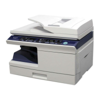
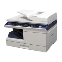
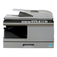
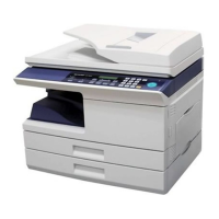
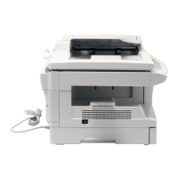
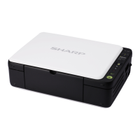
Shows external views and labels key components like trays and covers.
Illustrates the internal arrangement of major parts like TD and drum cartridges.
Details the keys, indicators, and display on the operation panel.
Explains the meaning of various indicators like Start, Power Save, and SCAN.
Lists and identifies main motors and solenoids with their functions.
Identifies sensors and switches and their functions within the machine.
Identifies different PWB units and their functions.
Illustrates the paper path and key components in a cross-sectional diagram.
Advises on environmental conditions and placement for installation.
Provides warnings on handling the copier and its sensitive parts.
Lists components to check after unpacking the machine.
Instructions for safely removing the unit from its packaging.
Details on removing tape and protective materials before use.
Step-by-step guide for installing the TD cartridge correctly.
Instructions for loading paper into the appropriate tray.
Guides on how to connect power and turn on the machine.
Instructions for installing printer and scanner drivers and utilities.
Lists the necessary computer hardware and operating system requirements.
Provides detailed instructions for installing the machine's software.
Steps to configure printer driver settings for paper size and type.
Guides on linking Button Manager to scanner functions for ease of use.
Details the USB connector and pin configuration for machine connectivity.
Provides guidance on safely moving the copier unit.
Describes the installation of a kit to prevent dew condensation in humid environments.
A diagram illustrating the basic operation cycle of the copier.
Explains the non-impact printing process using a semiconductor laser.
Breaks down the print process into detailed steps like charging, exposure, and developing.
Describes the basic configuration and flow of copy, print, and scan operations.
Details the scanner unit, optical system, and drive system.
Explains the laser unit's basic structure, beam path, and composition.
Describes the heat roller, separator pawls, and thermal control of the fuser.
Details the paper transport path and general operations for tray and manual feed.
Explains how the machine detects a new drum unit.
Details the SPF outline, document transport, and operational descriptions.
Procedures for disassembling and cleaning the high voltage section.
Steps to remove and reassemble the operation panel unit.
Procedures for disassembling and reassembling the optical scanning system.
Steps for disassembling and reassembling the fusing unit.
Procedures for disassembling the paper feed and transport mechanisms.
Steps to disassemble the manual paper feed unit.
Procedures for disassembling the rear frame and related parts.
Steps to disassemble and remove the power supply unit.
Procedures for disassembling the duplex motor unit.
Steps for disassembling the reverse roller section.
Procedures for disassembling the SPF unit and its motor.
Covers copy magnification ratio and image position adjustments.
Details how to adjust copy density for different modes.
Covers main charger (grid bias) and DV bias adjustments.
Adjusts paper reverse position and trailing edge void for duplex copying.
Automates the adjustment of the SPF scan position.
Adjusts the magnification ratio in the sub scanning direction for SPF.
Acquires target values for black level adjustment of white balance.
Instructions on how to access the service simulation modes.
Explains the usage of keys within the simulation mode.
A comprehensive list of available simulation modes and their functions.
Explains the function and operation of specific simulation modes.
Provides a list of trouble codes and their details for diagnostics.
Step-by-step instructions for setting and changing user program parameters.
Explains how to check the toner level using the display and keys.
Shows the main electrical components and their interconnections.
Provides detailed wiring diagrams for MCU PWB and SPF unit.
Lists signals, their names, functions, and associated sections.
Detailed circuit diagram for the Main Control Unit (MCU) Printed Wiring Board.
Circuit diagram for the Operation Panel (OPE) Printed Wiring Board.
Provides notes on using lead-free solder thread and soldering work.
Warnings and instructions for safely replacing the battery.
Guidelines for proper disposal of used batteries.
| Print Technology | Laser |
|---|---|
| Print Speed | 20 ppm |
| Copy Speed | 20 cpm |
| Max Print Resolution | 600 x 600 dpi |
| Max Copy Resolution | 600 x 600 dpi |
| Scan Resolution | 600 x 600 dpi |
| Paper Capacity | 250 sheets |
| Duplex Printing | Manual |
| Interface | USB 2.0 |
| Type | Monochrome |
| Functions | Print, Copy, Scan |
| Original Size | A4, Letter |
| Media Size | A4 |