6
Part names
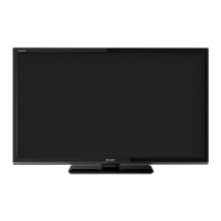
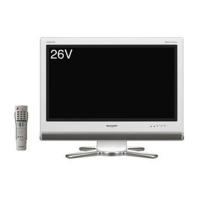
TV (Front)
Remote control sensor
Power Indicator
POWER indicator
Lighted (Red) The TV is off (standby mode).
Lighted (Green) The TV is on.
TV (Rear/Location of controls)
5
6
7
8
9
10
11
13 14
12
1
2
3
4
Warning: When
mounting the TV on a
wall, NEVER remove the
stand neck.
stand neck
1
/ENTER button
2 P (Channel)
/ / / buttons
3
(Volume) +/–/ / buttons,
MENU button
Press hold
(Volume) +/–
simultaneously about 1 second the
menu will be appear.
4
a
(Power) button
5 HEADPHONE jack (Ø 3.5 mm)
• The speakers do not output
volume when headphones are
plugged in.
6 USB terminal*
7 HDMI 1 Input terminal
• AUDIO PC/HDMI1/HDMI2 input
alternative
8 VIDEO/AUDIO Output terminal
• AV OUT jack is for RF or
COMPOSITE signal only. HDMI/
USB/YUV signal is not output.
9 COMPONENT/AV VIDEO Input
terminals
• Audio input alternative
10 ANT. (Antenna) input terminal
11 HDMI 2 Input terminal
12 PC Monitor Input
• Audio input mini pin jack
13 Bracket holes Fix a wall mounting
bracket (not supplied) here. Before
wall-mounting, please check
carefully the location of the TV’s
mounting-holes.
14 Power supply
*
USB terminal use for USB Media Player. (See page 13.)
• The illustrations in this operation manual are for explanation purposes and may vary slightly from the actual operations.
J3QQ1401C_EN.indd 6J3QQ1401C_EN.indd 6 5/27/2013 2:03:22 PM5/27/2013 2:03:22 PM