CD-C471 W
NOTES
ON
SCHEMATIC
DIAGRAM
l
Resistor:
To differentiate the units of resistors, such symbol as
K
and
M
are used: the symbol
K
means 1000 ohm and the symbol
M
means 1000 kohm and the resistor without any symbol is
ohm-type resistor. Besides, the one with “Fusible” is a fuse
type.
l
Capacitor:
To indicate the unit of capacitor, a symbol
P
is used: this
symbol
P
means micro-micro-farad and the unit of the
capacitor without such a symbol is microfarad. As to
electrolytic capacitor, the expression “capacitance/withstand
voltage” is used.
(CH), (TH),
(RH),
(UJ): Temperature compensation
(ML): Mylar type
(P.P.): Polypropylene type
l
Schematic diagram and Wiring Side of
P.W.Board
for this
model are subject to change for improvement without prior
notice.
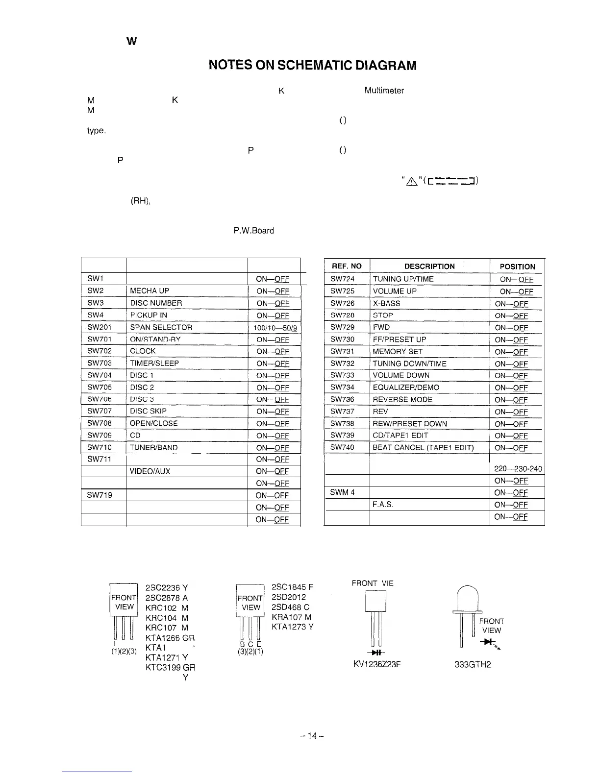
REF. NO DESCRIPTION
POSITION
SW1
OPEN/CLOSE
ON-W
SW71
1
TAPE
SW712
VIDEO/AUX
SW718
CENTER MODE/PHANTOM
SW719
CENTER MODE/NORMAL
SW721
DOLBY PRO LOGIC BYPASS
SW723
REC PAUSE
ON-E
ON-E
ON-m
ON-E
ON-CJj--J
ON--m
l
The indicated voltage in each section is the one measured
by Digital Multimeter between such a section and the chas-
sis with no signal given.
1. In the tuner section,
(
)
indicates AM
2. In the main section, a tape is being played back.
3. in the deck section, a tape is being played back.
(
)
indicates the record state.
4. In the power section, a tape is being played back.
5. In the CD section, the CD is stopped.
l
Parts marked with
“A
”
(
c
-
-
-
7)
are important for
-mm
maintaining the safety of the set. Be sure to replace these
parts with specified ones for maintaining the safety and
performance of the set.
/
SW801
/
VOLTAGE SELECTOR
1
110-127-
220-230-240
SWM 3 REC FWD
ON--~
SWM4
REC RVS
ON--E
SWM 5 F.A.S.
ON-W
SWM 6 CAM
ON--QE4
ECB
u)(2)(3)
KTAI
268 GR
KTA1271
Y
(3)(2x1)
+H-
KTC3199
GR
KVl236223F
KTC3203
Y
333GTH2
Figure 18 TYPES OF TRANSISTOR AND LED
-14-