CD-C602,CP-C602
– 9 –
MECHANISM SECTION
• Driving Force Check
Torque Meter
Specified Value
Play: TW-2412 Tape 1: Over 100 g
Tape 2: Over 50 g
• Torque Check
Torque Meter
Tape 2
Play: TW-2111 30 to 60 g. cm 30 to 60 g.cm
Fast forward: TW-2231 80 to 135 g.cm —
Rewind: TW-2231 80 to 135 g.cm —
Specified
Value
Adjusting
Point
Instrument
Connection
Test Tape
Normal MTT-111 Volume in 3,000 ± Speaker
speed motor 30 Hz terminal
(Load
resistance:
4 ohms)
ADJUSTMENT
Specified Value
Tape 1
• Tape Speed
• AM IF/RF
Signal generator: 400 Hz, 30%, AM modulated
*1. Input: Antenna (CNP301), Output: TP302
*2. Input: Antenna (CNP301), Output: TP301
TUNER SECTION
fL: Low-range frequency
fH: High-renge frequency
IF 450 kHz 1,720 kHz T351 *1
Band — 530 kHz (fL): T333 *2
Coverage 1.1 ± 0.1 V
Tracking 990 kHz 990 kHz (fL): T331 *1
Test Stage
Frequency Frequency
Display
Setting/
Adjusting
Parts
Instrument
Connection
*1. Input: Antenna (CNP301), Output: TP301
*2. Input: Antenna (CNP301), Output: Speaker terminal
• FM RF
Signal generator: 1 kHz, 22.5 kHz dev., FM modulated
Band — 87.50 MHz L303(fL): *1
Coverage 1.3 V ± 0.1 V
RF 98.00 MHz 98.00 MHz L302 *2
(10-30 dB)
Test Stage
Instrument
Connection
Frequency
Frequency
Display
Serring/
Adjusting
Point
• FM Detection
Signal generator: 10.7 MHz, FM sweep generator
Detection 10.7 MHz 98.00 MHz T352 Input: Pin 1 of
IC301
Output: TP302
IF 10.7 MHz 98.00 MHz T301(Turn Input: Pin 1 of
the core of IC301
transformer Output: TP302
T352 fully
counter-
clookwise.)
Instrument
Connection
Test
Stage
Adjusting
Parts
Frequency
Display
Frequency
Adjusting
Parts
Instrument
Connection
Frequency
Display
Frequency
• VCO Frequency
* Adjust for 76 kHz ± 200 Hz.
Notes:
After preparing the test circuit shown in Fig 9-3, connect the
Pin 13 , Pin 21 and ground of the IC351 with test circuit, and
measure the Value.
At this time, apply a standard unmodulated signal input and
adjust the VCO.
Pin 13 of IC351
Pin 21 of IC351
D
G
S
10 kohm
TO FREQUENCY
COUNTER
FET : 2SK19 or 2SK54
Figure 9-3
98.00 MHz 98.00 MHz VR351* Pin 13, Pin 21
(60 dB) and ground
of IC351
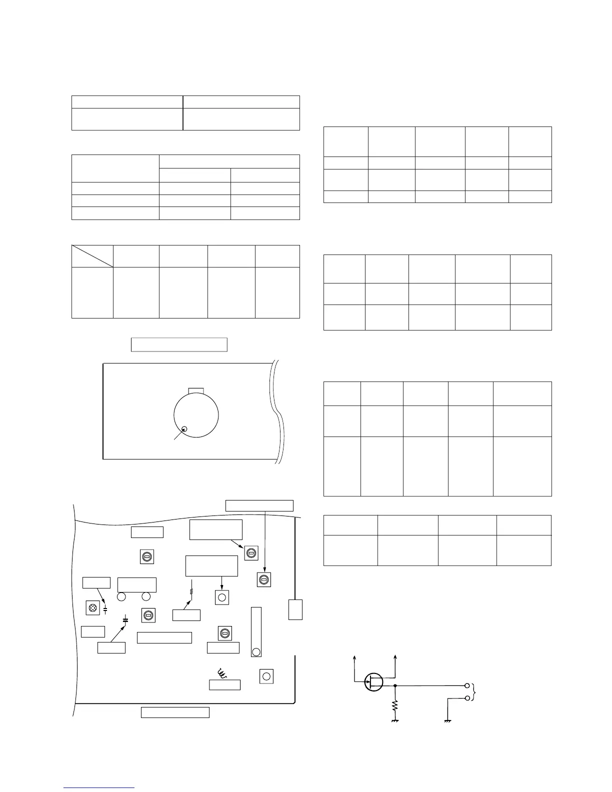
TAPE MECHANISM
Volume in motor
Figure 9-2 ADJUSTMENT POINTS
Figure 9-1 ADJUSTMENT POINTS
L303
R319
T331
T301
L301
L302
CNP301
FM/AM
ANTENNA
TERMINAL
T351
T333
IC351
IC301
FM RF
AM Tracking fL
VCO
AM IF
FM IF
VR351
FM Band
Coverage fL
FM Detection
AM Band
Coverage fL
T352
MAIN PWB
1
C360
C364
TP301
+
TP303
TP302
13
21