EasyManua.ls Logo

Sharp CD-K1861V

Sharp CD-K1861V
80 pages
To Next Page IconTo Next Page
Loading...
– 1 –
CD-K1861V
CONTENTS
Page
SAFETY PRECAUTION FOR SERVICE MANUAL ........................................................................................................... 2
VOLTAGE SELECTION..................................................................................................................................................... 2
SPECIFICATIONS ..............................................................................................................................................................3
NAMES OF PARTS ........................................................................................................................................................... 4
OPERATION MANUAL ...................................................................................................................................................... 6
DISASSEMBLY.................................................................................................................................................................. 7
REMOVING AND REINSTALLING THE MAIN PARTS..................................................................................................... 9
ADJUSTMENT ................................................................................................................................................................. 10
NOTES ON SCHEMATIC DIAGRAM .............................................................................................................................. 12
BLOCK DIAGRAM ........................................................................................................................................................... 13
SCHEMATIC DIAGRAM / WIRING SIDE OF P.W.BOARD..............................................................................................16
VOLTAGE ........................................................................................................................................................................ 40
WAVEFORMS OF CD CIRCUIT...................................................................................................................................... 41
TROUBLESHOOTING (CD SECTION) ........................................................................................................................... 42
FUNCTION TABLE OF IC................................................................................................................................................ 47
FL DISPLAY..................................................................................................................................................................... 63
PARTS GUIDE/EXPLODED VIEW
CD-K1861V
In the interests of user-safety the set should be restored to its
original condition and only parts identical to those specified be
used.
NTSC/PAL
SHARP CORPORATION
SERVICE MANUAL
No. S0959CDK1861V
This document has been published to be used
for after sales service only.
The contents are subject to change without notice.
CD-K1861V Video CD Mini System consisting of CD-K1861V
(main unit) and CP-C861(speaker system).
Question and Answer IconNeed help?

Do you have a question about the Sharp CD-K1861V and is the answer not in the manual?

Sharp CD-K1861V Specifications

General IconGeneral
CD PlayerYes
Cassette DeckYes
BluetoothNo
USB PortNo
Radio TunerFM
Playable MediaCD, Cassette
Speakers2 speakers

Summary

SHARP SERVICE MANUAL CD-K1861 V

Introduction and Overview

General introduction to the service manual and its contents.

Safety Precautions

Laser Safety Guidelines

Crucial safety measures regarding laser radiation exposure.

Voltage Selection Procedure

Instructions for selecting the correct AC voltage input for the unit.

System Specifications

Technical Details of CD-K1861 V and CP-C861

Detailed technical specifications for the main unit and speaker system.

Names of Parts - Main Unit

Front Panel Components

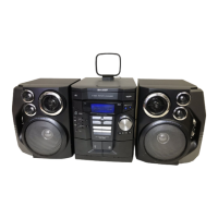
Identification and labeling of all controls and indicators on the front panel.

Component Identification

Rear Panel and Remote Control Layouts

Identification of rear panel connectors and remote control buttons.

Operation Manual Procedures

Setting the Clock and Resetting Microcomputer

Guides for setting the clock and resetting the unit's microcomputer.

Disassembly and Component Removal

Disassembly Cautions and Procedures

Essential safety warnings and initial steps for disassembling the unit.

Main Part Removal and Reinstallation

CD Mechanism Section Procedures

Detailed steps for removing and reinstalling the CD mechanism.

Adjustment Procedures

Mechanism and Tuner Section Adjustments

Specific adjustment steps for the mechanism and tuner sections.

Test Modes and CD Section Operation

Test Mode Setup and CD Diagnostics

Instructions for activating test modes and understanding CD section diagnostics.

Schematic Diagram Notes

Conventions for Schematic Diagrams

Explains symbols, abbreviations, and notes used in schematic diagrams.

Block Diagrams - System Overview

Pickup, Servo, and Control Circuits

Block diagram illustrating the pickup unit, servo amplifier, and control circuits.

Block Diagrams - Signal Processing

Tuner, Audio, and Tape Sections

Block diagram showing signal flow for tuner, audio, and tape functions.

Block Diagrams - Power and Microcomputer

Power Supply and System Control

Block diagram covering power supply and system control microcomputer connections.

Schematic Diagrams - Main PWB

Main PWB Schematic Diagram (Part 1)

Detailed circuit diagram for the main printed wiring board.

Schematic Diagrams - Tuner PWB

Tuner PWB Schematic Diagram

Detailed circuit diagram for the tuner printed wiring board.

Wiring Side of P.W.Board - Tuner

Tuner PWB Component Layout

Shows component placement and wiring on the tuner PWB.

Wiring Side of P.W.Board - Main

Main PWB Component Layout (Part 1)

Component placement and wiring on the main PWB.

Wiring Side of P.W.Board - DisplaySwitch

Display and Switch PWB Component Layout

Component placement and wiring for display and switch PWBs.

Wiring Side of P.W.Board - Power Supply

Power Supply PWB Component Layout

Component placement and wiring on the power supply PWB.

Wiring Side of P.W.Board - Power Amp

Power Amplifier PWB Component Layout

Component placement and wiring on the power amplifier PWB.

Voltage Measurement Points

IC Pin Voltage Table

Reference table for expected voltages at various IC pins during operation.

CD Circuit Waveform Analysis

Waveform Examples for Troubleshooting

Visual representations of CD circuit waveforms for diagnostic purposes.

Troubleshooting - CD Section Issues

CD Functionality and Cleaning

Resolving CD playback issues and proper cleaning methods.

Troubleshooting - Turntable Operation

Turntable Stop and Movement Problems

Diagnosing and fixing failures related to the turntable's rotation.

Troubleshooting - CD Tray and Keypad

CD Tray and Key Operation Failures

Troubleshooting CD tray mechanism and keypad response issues.

Troubleshooting - CD Playback Performance

Disc Load Playback and Tracking System

Addressing playback issues after disc load and checking the tracking system.

Troubleshooting - CD Disc Read Issues

Spin System, VCOPLL, and Sound Output

Diagnosing spin system, VCO/PLL, and no-sound issues.

IC Function Tables

IC1 Servo Amplifier Pin Functions

Detailed pinout and function description for the IC1 Servo Amplifier.

Integrated Circuit Block Diagrams

MIC AMP, Ope Amp, and Audio Processor ICs

Block diagrams for MIC AMP, Operational Amplifier, and Audio Processor ICs.

Parts Guide and Ordering Information

Parts Ordering and Component Code Explanations

Guidance on ordering parts and understanding component code conventions.

Exploded Views - CD Mechanism

CD Mechanism Assembly Diagram

Illustrated breakdown of the CD mechanism components for assembly reference.

Exploded Views - Main Unit Cabinet

Main Unit Cabinet Assembly Diagram (Part 1)

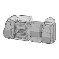
Illustrated breakdown of the main unit cabinet components.

Exploded Views - Speaker System

CP-C861 Speaker Assembly Diagram

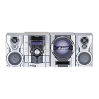
Illustrated breakdown of the CP-C861 speaker system components.

Related product manuals