EasyManua.ls Logo

Sharp CD-K7000W User Manual

Sharp CD-K7000W
68 pages
To Next Page IconTo Next Page
Page #1 background imageLoading...
Page #1 background image
– 1 –
CD-K7000W/C7000W,CP-C7000
No. S3022CDK7000W
CONTENTS
Page
SAFETY PRECAUTION FOR SERVICE MANUAL ........................................................................................................... 2
VOLTAGE SELECTION ..................................................................................................................................................... 2
SPECIFICATIONS ............................................................................................................................................................. 3
NAMES OF PARTS ........................................................................................................................................................... 4
OPERATION MANUAL ...................................................................................................................................................... 8
DISASSEMBLY.................................................................................................................................................................. 9
REMOVING AND REINSTALLING THE MAIN PARTS ................................................................................................... 12
ADJUSTMENT ................................................................................................................................................................. 14
NOTES ON SCHEMATIC DIAGRAM .............................................................................................................................. 16
BLOCK DIAGRAM ........................................................................................................................................................... 17
SCHEMATIC DIAGRAM / WIRING SIDE OF P.W.BOARD ............................................................................................. 21
VOLTAGE ........................................................................................................................................................................ 40
WAVEFORMS OF CD CIRCUIT ...................................................................................................................................... 41
TROUBLESHOOTING (CD SECTION) ........................................................................................................................... 42
FUNCTION TABLE OF IC................................................................................................................................................ 46
FL DISPLAY ..................................................................................................................................................................... 54
REPLACEMENT PARTS LIST/EXPLODED VIEW
CD-K7000W
CD-C7000W
CP-C7000
In the interests of user-safety the set should be restored to its
original condition and only parts identical to those specified be
used.
SERVICE MANUAL
This document has been published to be used
for after sales service only.
The contents are subject to change without notice.
SHARP CORPORATION
Illustration: CD-K7000W/CP-C7000
Illustration: CD-C7000W/CP-C7000
DIFFERENCE BETWEEN CD-K7000W AND CD-C7000W
CD-K7000W
CD-C7000W
Karaoke
Question and Answer IconNeed help?

Do you have a question about the Sharp CD-K7000W and is the answer not in the manual?

Sharp CD-K7000W Specifications

General IconGeneral
CD PlayerYes
Radio TunerAM/FM
Remote ControlYes
Cassette DeckDual
TypeMini Component System
Speakers2-Way Speaker System

Summary

Safety Precautions for Service Manual

Laser Safety Warnings

Precautions for handling the laser component to prevent eye exposure during servicing.

Voltage Selection

Procedure for selecting the correct AC voltage for the unit's operation.

Specifications

Names of Parts

CD-K7000W Front Panel Parts

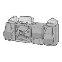
Identification and numbering of front panel components for the CD-K7000W model.

CD-C7000W Front Panel Parts

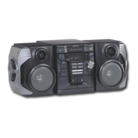
Identification and numbering of front panel components for the CD-C7000W model.

Component Identification

Identification of rear panel, speaker, and remote control parts for various models.

Operation Manual

Setting the Clock

Step-by-step guide for setting the unit's clock time.

Resetting the Microcomputer

Procedure for resetting the microcomputer to clear memory and settings.

Disassembly

Caution on Disassembly

Important notes and precautions to follow during disassembly procedures.

CD Mechanism Disassembly

Detailed steps for disassembling the CD mechanism components.

Removing and Reinstalling Main Parts

Tape Mechanism Section

Instructions for removing and reinstalling tape mechanism components.

CD Mechanism Section

Instructions for removing and reinstalling CD mechanism components.

Adjustment

Mechanism Section Adjustment

Procedures for checking and adjusting mechanism driving force and tape speed.

Tuner Section Adjustment

Procedures for adjusting AM IF/RF and FM RF signals.

CD Section Adjustment

Automatic CD Adjustments

Details on automatically adjusted functions like offset, balance, and gain.

Notes on Schematic Diagram

Block Diagrams

Block Diagram (1/4)

Schematic representation of the CD system's main signal flow.

Block Diagram (2/4)

Schematic representation of tuner and audio processor signal flow.

Block Diagram (3/4)

Schematic representation of system microcomputer and power supply.

Block Diagram (4/4)

Schematic representation of CD-K7000W microphone section signal flow.

Troubleshooting

When the CD Does Not Function

Steps to take when the CD section is not operating correctly.

When a CD Cannot Be Played

Troubleshooting guide for issues preventing CD playback.

Focus-HF System Check

Procedure to check the focus-HF system for CD playback issues.

Tracking System Check

Procedure to check the tracking system for CD playback issues.

Spin System Check

Procedure to check the spin system for CD playback issues.

PLL System Check

Procedure to check the PLL system for CD playback issues.

Other CD Playback Issues

Troubleshooting for no sound or sound dropouts during CD playback.

Function Table of ICs

IC1 Servo Amplifier (LA9235M)

Function table and block diagram for the servo amplifier IC.

IC2 Servo/Signal Control (LC78641E)

Function table and block diagram for the servo/signal control IC.

Sharp Parts Guide

How to Order Replacement Parts

Information and contact details for ordering replacement parts.

Capacitor and Resistor Parts Codes

Explanation of codes used for identifying capacitor and resistor parts.

Parts Code Listing

Integrated Circuits and Transistors

List of integrated circuits and transistors with their part codes.

Capacitors and Resistors

List of capacitors and resistors with their part codes.

Exploded Views

CD Mechanism Exploded View

Diagram showing the assembly of CD mechanism components.

Cabinet Exploded View

Diagram showing the assembly of the main unit's cabinet.

Speaker Exploded View

Diagram showing the assembly of CP-C7000 speaker components.

Related product manuals