Do you have a question about the Sharp CD-K491W and is the answer not in the manual?
Essential safety precautions for servicing the unit to prevent hazards.
Instructions for selecting the correct AC voltage input for the unit.
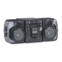
Overall power, dimensions, and weight details for the main unit.
Output power, input terminals, and speaker impedance details.
Technical details for CD player, tuner, and cassette deck sections.
Details for front, center, surround, and subwoofer speaker units.
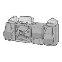
Identification of buttons, indicators, and displays on the front panel.
Identification of input/output sockets and speaker terminals on the rear panel.
Identification of parts for front, center, surround, and subwoofer speakers.
Identification of buttons and functions on the remote control unit.
Step-by-step guide to set the unit's internal clock time.
Procedure to set the FM/MW tuning interval span based on region.
Instructions for resetting the unit's internal microcomputer and memory.
Important precautions to follow before and during unit disassembly.
Detailed steps for removing various parts like cabinets, PWBs, and mechanisms.
Procedures for removing the CD mechanism, loading motor, and pickup unit.
Adjustments for tape mechanism driving force and speed.
Alignment procedures for AM IF/RF, FM RF, FM detection, and mute level.
Setting and operation of the CD test mode for diagnostics.
Automatic adjustment items for focus, tracking, and RF level.
Information on different Dolby digital signal inputs and channel configurations.
Explains Normal, Phantom, Virtual, and Enhanced Virtual Surround modes.
Explanation of symbols used for resistors, capacitors, and other components.
Identification of common transistors and LEDs used in the unit.
Block diagram illustrating the CD pickup unit and servo control circuits.
Block diagram showing analog input filters and A/D, D/A converter sections.
Block diagram for Dolby AC-3 decoder, amplifier stages, and power supply regulation.
Block diagram illustrating the tuner circuit, PLL controller, and audio processing.
Block diagram showing the microcomputer, display drivers, and power supply system.
Detailed schematic of the CD servo amplifier circuit and related components.
Detailed schematic of the CD servo PWB, including ICs and discrete components.
Schematic showing the microcomputer connections to various peripherals.
Schematic details of the pre-amplifier stages and volume control circuitry.
Schematic illustrating the control signals and circuitry for the tape mechanism.
Schematic of the tape playback and record amplifier circuits.
Schematic for input/output buffer amplifiers and mute control circuits.
Schematic details for speaker amplifier power supply and regulation circuits.
Schematic of the graphic equalizer and volume control circuits.
Schematic for the Q-Sound decoder IC and related components.
Schematic details for the microphone amplifier and echo control circuits.
Detailed schematic of the tuner Printed Wiring Board (PWB).
Schematic showing digital inputs and Dolby processing sections.
Schematic of the audio decoder and amplifier stages.
Schematic for the display and switch PWBs, including microcomputer.
Schematic detailing the remote sensor and button input circuitry.
Schematic diagrams for the speaker amplifier circuits.
Schematic details for speaker amplifier power output stages and speaker terminals.
Schematic illustrating the various voltage regulators and power supply circuits.
Schematic of the power transformer, AC input, and voltage selection circuits.
Wiring layout for the main PWB (Part A).
Continued wiring layout for the main PWB (Part A).
Wiring layout for the headphones and jog control PWBs.
Wiring layout for the display and switch PWBs.
Wiring layout for the Dolby PWB (Part G).
Wiring layout for sensor, CD motor, and CD servo PWBs.
Wiring layout for the tuner PWB (Part E).
Wiring layout for the karaoke PWB and tape mechanism.
Wiring layout for the speaker amplifier PWBs (F1 and F2).
Wiring layout for the power PWB (Part D).
Oscilloscope waveforms related to focus and tracking servo operations.
Oscilloscope waveforms for RF signal, CLV, and spindle motor control.
Diagnostic steps for when the turntable fails to stop correctly.
Diagnostic steps for when the turntable fails to move or rotate.
Troubleshooting steps for CD tray open/close mechanism failures.
Troubleshooting for non-functional CD operating keys and function issues.
Diagnosis for playback problems, focus servo, DRF signal, and HF waveform.
Steps to check and diagnose tracking system performance and servo issues.
Procedures to check the disc spin system and turntable rotation.
Steps to diagnose issues with the VCO-PLL system for TOC reading.
Diagnosis for cases where no sound is emitted despite normal waveforms.
Pin functions and descriptions for the IC2 servo/signal control IC.
Continued pin functions for the IC2 servo/signal control IC.
Pin functions and descriptions for the IC1 servo amplifier.
Continued pin functions for the IC1 servo amplifier.
Pin functions and descriptions for the ICQ01 Q-Sound decoder IC.
Pin functions and descriptions for the ICF01 system microcomputer.
Pin functions and descriptions for the ICD01 system microcomputer.
Continued pin functions for the ICD01 system microcomputer.
Pin functions and descriptions for the ICA18 Dolby decoder IC.
Continued pin functions for the ICA18 Dolby decoder IC.
Table showing the mapping of pins to segments for the FL display.
Explanation of the coding system for capacitor part numbers.
Explanation of the coding system for resistor part numbers.
List of integrated circuits with part codes, ranks, and descriptions.
List of transistors with part codes, ranks, and descriptions.
List of diodes with part codes, ranks, and descriptions.
List of coils with part codes, ranks, and descriptions.
List of variable resistors with part codes, ranks, and descriptions.
List of variable capacitors with part codes, ranks, and descriptions.
List of capacitors with part codes, ranks, and descriptions.
List of resistors with part codes, ranks, and descriptions.
List of resistors with part codes, ranks, and descriptions.
List of resistors with part codes, ranks, and descriptions.
List of resistors with part codes, ranks, and descriptions.
List of connectors, switches, and other miscellaneous parts.
List of switches with part codes, ranks, and descriptions.
List of parts specific to the CD mechanism assembly.
List of cabinet parts and panels used in the unit assembly.
List of parts for the CP-K491 front speaker system.
List of parts for the CP-SW491 subwoofer.
List of parts for the center speaker system.
List of parts for the surround speaker system.
Exploded view showing the assembly of the CD mechanism components.
Exploded view of the main unit's cabinet and internal PWB layout.
Exploded view showing chassis, CD mechanism, and motors.
Exploded view of the CP-K491 front speaker system components.
Exploded view of the CP-SW491 subwoofer components.
Exploded views of the center and rear speaker system components.
| Brand | Sharp |
|---|---|
| Model | CD-K491W |
| Category | Stereo System |
| Language | English |