– 9 –
CD-K1861V
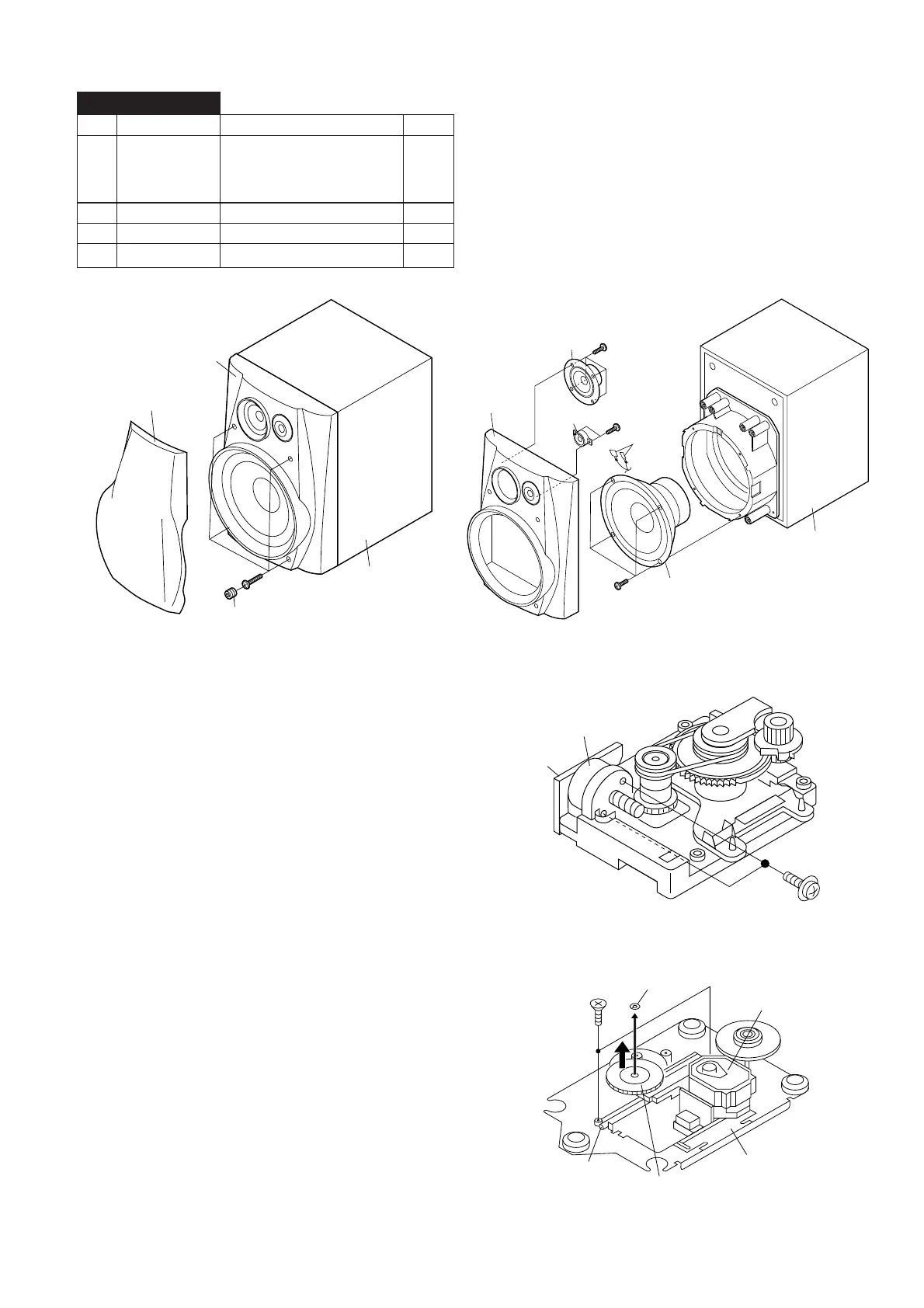
1 Front Panel 1. Net.......................... (A1) x1 9-1
2. Rubber ................... (A2) x4
3. Screw ..................... (A3) x4
4. Tip .......................... (A4) x4 9-2
2 Woofer 1. Screw ..................... (B1) x4 9-2
3 Tweeter 1. Screw ..................... (C1) x4 9-2
4 Super Tweeter 1. Screw ..................... (D1) x2 9-2
STEP REMOVAL
PROCEDURE
FIGURE
Figure 9-1 Figure 9-2
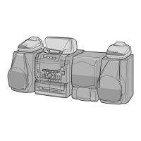
How to remove the pickup (See Fig. 9-4)
1. Remove the screws (B1) x 2 pcs., to remove the shaft (B2).
2. Remove the stop washer (B3) x 1 pc., to remove the gear
(B4).
3. Remove the pickup.
Figure 9-4
REMOVING AND REINSTALLING THE MAIN PARTS
CD MECHANISM SECTION
Perform steps 1, 2, 3, 12, 13, 14, 15 and 16 of the disassembly
method to remove the CD mechanism.
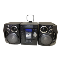
How to remove the loading motor
(See Fig. 9-3)
1. Remove the screws (A1) x 2 pcs., to remove the loading
motor.
Figure 9-3
Note
After removing the connector for the optical pickup from the
connector, wrap the conductive aluminium foil around the
front end of connector to protect the optical pickup from
electrostatic damage.
(A1) x2
ø2.6 x5mm
Loading Motor
Motor
PWB
(B1) x2
ø2.6 x6mm
Shaft
(B2) x1
Stop Washer
(B3) x1
Gear
(B4) x1
CD Mechanism
Pickup
CP-C861
(A1)x1
Front Panel
(A3)x4
ø4x18mm
(A2)x4
Cabinet
Front Panel
Tweeter
Super
Tweeter
(C1)x4
ø3x10mm
(D1)x2
ø3x10mm
Woofer
(B1)x4
ø4x12mm
(A4)x4
Cabinet