CD-XP205V
No. S7256CDXP205V
CONTENTS
Page
SAFETY PRECAUTION FOR SERVICE MANUAL ........................................................................................................... 2
VOLTAGE SELECTION..................................................................................................................................................... 2
AC POWER SUPPLY CORD AND AC PLUG ADAPTOR ................................................................................................. 2
SPECIFICATIONS ............................................................................................................................................................. 3
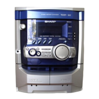
NAMES OF PARTS ........................................................................................................................................................... 4
DISASSEMBLY.................................................................................................................................................................. 6
REMOVING AND REINSTALLING THE MAIN PARTS..................................................................................................... 9
ADJUSTMENT ................................................................................................................................................................. 10
BLOCK DIAGRAM ........................................................................................................................................................... 15
SCHEMATIC DIAGRAM / WIRING SIDE OF P.W.BOARD............................................................................................. 18
NOTES ON SCHEMATIC DIAGRAM .............................................................................................................................. 39
TYPES OF TRANSISTOR AND LED............................................................................................................................... 39
VOLTAGE ........................................................................................................................................................................ 40
WAVEFORMS OF CD CIRCUIT...................................................................................................................................... 41
TROUBLESHOOTING ..................................................................................................................................................... 42
FUNCTION TABLE OF IC................................................................................................................................................ 46
FL DISPLAY..................................................................................................................................................................... 56
REPLACEMENT PARTS LIST/EXPLODED VIEW
SERVICE MANUAL
This document has been published to be used
for after sales service only.
The contents are subject to change without notice.
SHARP CORPORATION
• In the interests of user-safety the set should be restored to its
original condition and only parts identical to those specified be
used.
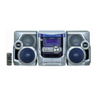
VIDEO CD MINI SYSTEM
MODEL CD-XP205V
CD-XP205V Video CD Mini System consisting of CD-XP205V
(main unit) and CP-XP205 (speaker system).
NTSC/PAL