EasyManua.ls Logo

Sharp CD-XP2200

Sharp CD-XP2200
64 pages
To Next Page IconTo Next Page
Loading...
CD-XP200/CD-XP2200
No. S1206CDXP200/
CONTENTS
Page
IMPORTANT SERVICE NOTES (FOR U.S.A. ONLY)....................................................................................................... 2
SPECIFICATIONS ............................................................................................................................................................. 3
NAMES OF PARTS ........................................................................................................................................................... 4
OPERATION MANUAL ...................................................................................................................................................... 6
QUICK GUIDE (FOR U.S.A. ONLY) .................................................................................................................................. 8
DISASSEMBLY................................................................................................................................................................ 10
REMOVING AND REINSTALLING THE MAIN PARTS................................................................................................... 13
ADJUSTMENT ................................................................................................................................................................. 14
NOTES ON SCHEMATIC DIAGRAM .............................................................................................................................. 18
TYPES OF TRANSISTOR AND LED............................................................................................................................... 18
BLOCK DIAGRAM ........................................................................................................................................................... 19
SCHEMATIC DIAGRAM / WIRING SIDE OF P.W.BOARD ............................................................................................. 22
VOLTAGE ........................................................................................................................................................................ 39
WAVEFORMS OF CD CIRCUIT ...................................................................................................................................... 40
TROUBLESHOOTING ..................................................................................................................................................... 41
FUNCTION TABLE OF IC................................................................................................................................................ 45
FL DISPLAY ..................................................................................................................................................................... 51
REPLACEMENT PARTS LIST/EXPLODED VIEW
PACKING OF THE SET (FOR U.S.A. ONLY)
SERVICE MANUAL
This document has been published to be used
for after sales service only.
The contents are subject to change without notice.
SHARP CORPORATION
In the interests of user-safety the set should be restored to its
original condition and only parts identical to those specified be
used.
MINI COMPONENT SYSTEM
MODEL CD-XP200
CD-XP200 Mini Component System consisting of CD-XP200
(main unit) and CP-XP200 (speaker system).
MINI COMPONENT SYSTEM
MODEL CD-XP2200
CD-XP2200 Mini Component System consisting of CD-XP2200
(main unit) and CP-XP2200 (speaker system).
Question and Answer IconNeed help?

Do you have a question about the Sharp CD-XP2200 and is the answer not in the manual?

Sharp CD-XP2200 Specifications

General IconGeneral
CD PlayerYes
Playable MediaCD, CD-R, CD-RW
BluetoothNo
USB PortNo
Cassette DeckYes
Radio TunerFM
Speakers2-Way Speakers

Summary

SHARP SERVICE MANUAL

IMPORTANT SERVICE NOTES (FOR U.S.A. ONLY)

Crucial safety information and checks for audio product service.

SPECIFICATIONS

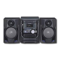
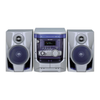
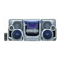
Technical details for the main audio unit's functions and speakers.

NAMES OF PARTS

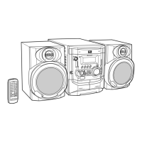
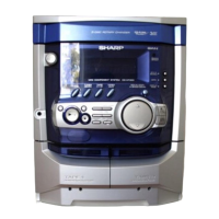
Identifies display elements, front panel controls, and rear panel connectors.

REMOTE CONTROL AND SPEAKER PARTS

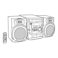
Identifies remote control buttons and functions, and speaker system components.

OPERATION MANUAL AND TROUBLESHOOTING

Guide for setting the clock and initial troubleshooting steps for common issues.

TROUBLESHOOTING AND MAINTENANCE

Instructions for system memory reset and preparing the unit for transport.

QUICK GUIDE AND SYSTEM SETUP

Instructions for accessories, battery installation, and system connections.

SYSTEM OPERATION

Steps for initial activation and basic playback of CDs, radio, and tapes.

DISASSEMBLY PROCEDURES

Detailed steps for disassembling main unit and speaker components.

REMOVING AND REINSTALLING MAJOR PARTS

Procedures for removing main parts, including tape mechanism components.

ADJUSTMENT PROCEDURES

Steps for CD mechanism adjustment and tape speed/torque calibration.

TUNER AND CD SECTION CALIBRATION

Calibration steps for tuner sections and automatic CD adjustments.

TEST MODE OPERATION

Instructions for entering and performing CD test mode.

SYSTEM ERROR MESSAGES AND DISPLAYS

Explanations for system error codes and status indicators.

SCHEMATIC DIAGRAM NOTES AND REFERENCES

Explanations for component codes and types used in schematics.

BLOCK DIAGRAMS

Diagrams illustrating the system's block-level architecture.

SCHEMATIC DIAGRAMS (110 - 1010)

Detailed circuit diagrams for various sections of the unit.

WIRING SIDE OF P.W.BOARDS (17 - 77)

Views showing the wiring and component placement on PCBs.

VOLTAGE MEASUREMENT TABLE

Table listing voltage measurements at various IC pins.

CD CIRCUIT WAVEFORMS

Illustrations of typical waveforms found in the CD circuit.

TROUBLESHOOTING GUIDE

Steps to diagnose and resolve CD section and playback problems.

CD SYSTEM FOCUS AND PICKUP CHECKS

Procedures for checking focus, pickup, laser, and turntable operation.

CD SYSTEM TRACKING AND SPIN CHECKS

Checks for tracking, spin systems, and PLL performance.

CD SYSTEM PLL AND OTHER CHECKS

Verifies PLL system, TOC data, and addresses sound output issues.

INTEGRATED CIRCUIT INFORMATION

Function tables and block diagrams for key integrated circuits.

PARTS LIST AND ORDERING INFORMATION

Guide for identifying and ordering replacement parts from SHARP.

EXPLODED VIEWS OF COMPONENTS

Visual diagrams of CD mechanism, cabinet, and speaker assemblies.

SET PACKING INSTRUCTIONS (FOR U.S.A. ONLY)

Guidelines for packing the set for shipment.

Related product manuals