A
ll
and more about Sharp PC-1500
at
http://www.PC-1500.info
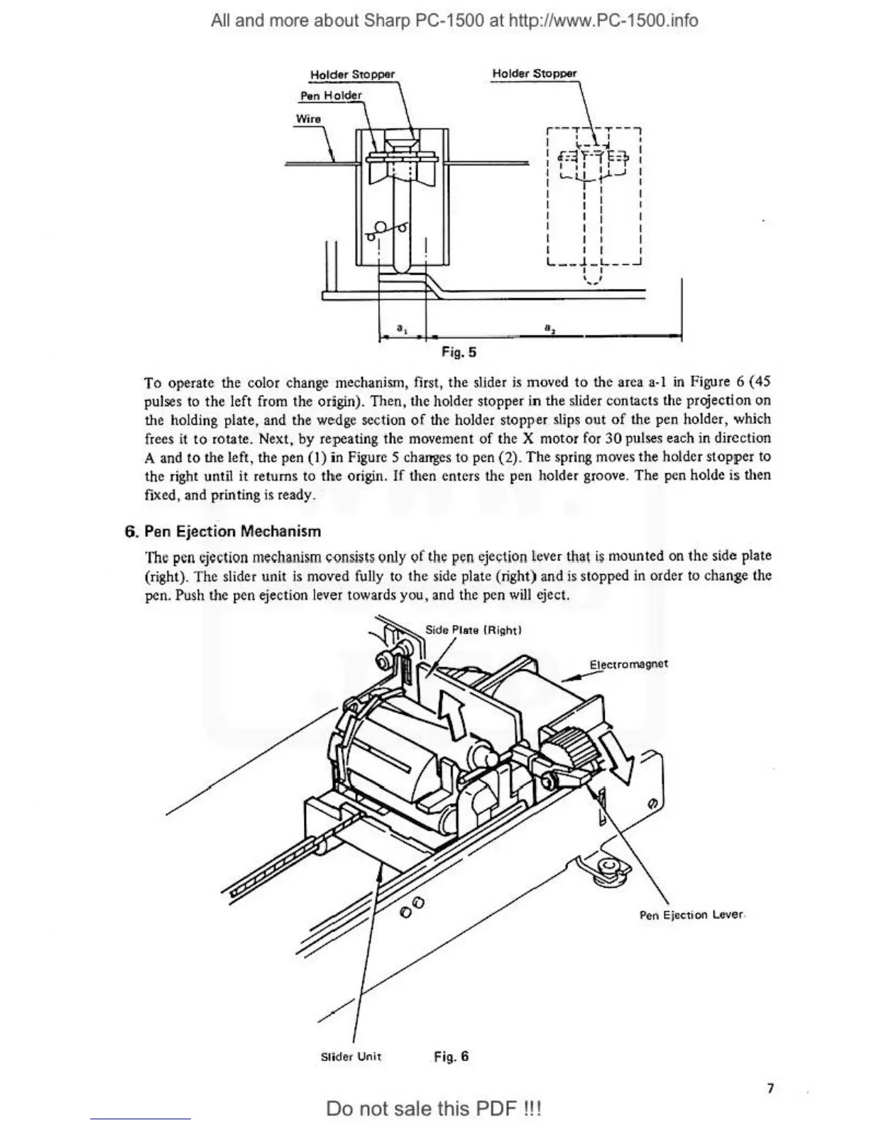
Holder Stopper
Wire
r--"T
-T--,
I
' I o
~-
-.I
I
I
I
·=~
"f._
''l"E
:>-
I
I
1
J I ·r
I
'-'+-re-'
:
I I I I
I I I
I I
I
I I I
I I I
l
I I I
J
~~~~~~~:=:=
:=:=:=~L~
-~-~J-~
--~
I I
i--:'
'
--+--
~
-
·,
.__=-_j
Fig.
5
To
operate the color change mechanism, first, t
he
slider is moved
to
the area a· l
in
Figure 6 ( 45
pulses to the left from the
or
igin). Then, the holder stopper in the
sl
ider contacts the projection on
the holding plate, and the wedge section
of
the holder stopper slips
out
of
the pen holde
r,
which
frees
it
to
ro
tate. Next, by repeating the movement
of
the X motor for
30
pulses each
in
direction
A and
to
the left, the pen
(I)
in Figure 5 changes to pen (2).
The
spring moves the holder stopper to
th
e right until
it
returns to the
or
igin.
If
then enters the pen
ho
ld
er
groove. The pen holde is then
fixed,
an
d printing is
rea
dy.
6. Pen Ejection Mechanism
Th
e pen ejection mechanism c-onsists
<.>tily
of
!he pen ejection lever
11131
is mounted on the side plate
(r
ight). The slider unit is moved fully to the side plate (ri
gh
t) and
is
stopped
ill
order to change the
pen.
Push the pen ejection lever towards you, and
th
e pen w
ill
eject.
P
en
Ejection LO'i'er.
Sli
det
Unit Fig. 6
7
Do not sale this PDF
!!
!