A
ll
and more about Sharp PC-1500
at
http://www.PC-1500.info
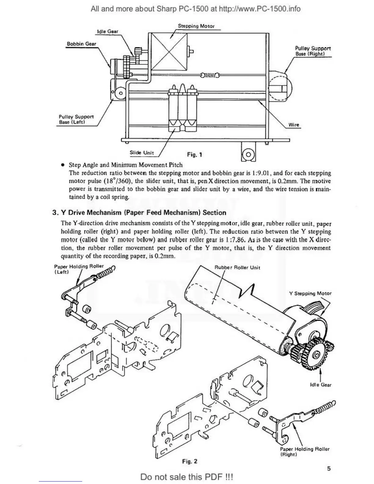
Bobbin
Ge
ar
Pulley Support
Base (Lettt
Idle
Gear
Stepping
Motor
Slide
Un
it
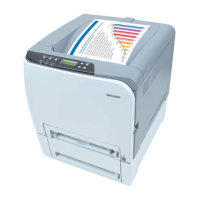
Fig.
1
• Step Angle and Minimum Movement Pitch
'
---
0
Pulley
SUJpport
B<:ite
(A.
ht)
Wire
The reduction ratio between the stepping motor and bobbin gear is I :9.01 , and for each stepping
motor pulse (18°/
360
),
the slider unit,
that
is, penX direction movement,
is
0.2mm. The motive
power
ls
transmitted to
the
bobbin gear and slider unit by a wire, and the wire tension is main-
t;iined
by a coil spring.
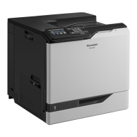
3.
Y Drive Mechanism (Paper Feed Mechanism) Section
The Y ·direction drive mechanism consists
of
the Y stepping
motor
,
idl
e gear, rubber roller uni
t,
paper
holding roller
(fight) and paper holding roller (left). The reduction ratio between the Y stepping
motor
(called
the
Y
mot
or
below)
and
rubber
r
olle
r
gea
r
is
l
:7.8
6.
As
is
the
case
wi
th the X dir
ec-
tion, the rubber roller movement per pulse
of
the Y motor,
that
is
, the Y diteclion movement
quantity
of the recording paper,
is
0.2mm.
Paper Holding Roller
(Left)
Fig.
2
5
Do not sale this PDF
!!
!