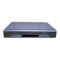
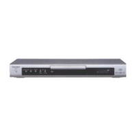
DV-600S
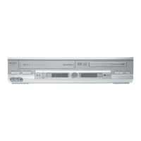
DV-600H
10-2
FLOW CHART NO.9
The operation from the remote control is disabled.
Although the operation on the deck is possible, the
remote control operation is disabled.
No Replace the remote control transmitter (take proper
measures as necessary).
Yes
No
Is 5V voltage supplied to the pin 3 terminal of
remote control receiver?
Check AT 5V line.
Yes
No
Is 'L' pulse signal generated from the pin 1 terminal
of receiver when the remote control transmitter is
operated?
Replace the remote control receiver.
Yes
No
Is pulse signal supplied to the pin 32 of IC504?
Check the line between the remote control receiver
and the IC504 pin 32.
Yes
Replace IC504.
FLOW CHART NO.10
AUDIO 9V is not output.
Is 12V voltage supplied to the IC9001 pin 3?
No
Check the secondary circuit AT 12V line.
Yes
Is there output to the IC9001 pin 1?
No
Check the IC9001 periphery circuit and AT 12V line.
Refer to the flow chart No.2 <The power cannot be
turned on>.
Replace Q9001.
FLOW CHART NO.11
PC 3.3V is not output.
No
Is 5V voltage supplied to the IC9003 pin 1?
Check the secondary circuit AT 5V line.
Yes
Is there output to the IC9003 pin 2?
No
Check the IC9003 periphery circuit and AT 5V line.
Yes
Check for load circuit short-circuiting or leak.
No
Check the periphery circuit when Q9001 is heated.
Yes
Is 9V voltage output to the Q9001 collector?
No
Check for load circuit short-circuiting or leak.
No
FLOW CHART NO.12
The disc tray cannot be opened and closed.
No
Is the signal from the IC504 pins 70 and 69 input
into the IC702 pins 6 and 7?
Check the LD-REV/FWD signal line between the
IC702 and the IC504.
Yes
No
Is the loading motor drive voltage output from the
IC702 pins 10 and 11?
Is 8V voltage applied to the IC702 pin 21?
Yes
No
Is the loading motor drive voltage applied to the
AG connector pins 3 and 2?
Check the line between the IC702 and the AG connector.
Yes
Yes
Check for mechanism and gear engagement and
breakage.
Replace IC702.
Check AT 8V line.
No
Yes
Check the connection of optical pickup cable.
If it is normal, replace the optical pickup.
No
No
Is the Q301 (LD POWER ON) drive signal (SEL)
output to the IC707 pin 52?
Is the Q307 (LD POWER CTL) drive signal (LDO1)
output to the IC303 pin 45?(Checking of symptom)
Is 3.3V voltage applied to the Q301 emitter? Is 5V
voltage applied to the Q307 emitter?
Yes
Yes
Are 3.3V and 2.3V voltages applied to the AB
connector pin 11 and 9, respectively?
Check the D 3.3V (1) line and the A 5V line.
FLOW CHART NO.15
The disc is ejected.
(When the laser beam does not light.)
Check the line between the IC707 pin 52 and the Q301
base through Q304.
heck the line between the IC303 pin 45 and the Q307 base.
No
Check the line between the Q301 and Q307, AB connector.
No
No
No
Yes
Is FE signal input into the IC707 pin 38?
(Checking of symptom)
Check the line between the IC303 pin 21 and the IC707 pin 38.
Yes
Yes
Is the focus control signal output to the IC707 pin 43?
Check the IC707 power source periphery circuit.
If it is normal, replace IC707.
Is the focus control signal from the IC504 pin 43
input into the IC702 pin 19?
Check the focus control signal (FOO) line between the
IC702 and the IC504.
Yes
No
Check the line between the IC702 and the AB connector.
No
Is the focus control drive voltage output from the
IC702 pins 17 and 18?
Yes
Is the focus control drive voltage applied to the AB
connector pins 4 and 2?
Yes
Check the connection of optical pickup cable.
If it is normal, replace the optical pickup.
No
No
No
No
The disc is ejected.
(In case of focus error)
Does the optical pickup move up and down after the
disc is removed? (Checking of symptom).
Refer to (When the focus servo does not function).
Yes
Yes
Yes
Is FE signal output to the IC303 pin 21 when the
disc is set?
Is there input signal on the IC303 pins (49, 54), (50, 55),
(46, 52), and (47, 53)?
Is there output signal on the IC301 pins 18, 17, 16, and 15?
Check the connection of optical pickup cable.
If it is normal, replace the optical pickup.
FLOW CHART NO.13
FLOW CHART NO.14
The disc is ejected.
(In case of focus error)
Is 8V voltage applied to the IC702 pin 21?
Yes
Replace IC702.
Check AT 8V line.
No