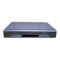
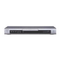
DV-600S
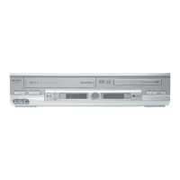
DV-600H
11-6. IC501 IX1539GE FLASH
Symbol Type Name and function
Byte selection address: When the device is in the x8 mode, the low or high order byte is
DQ
15
/A
-1
Input selected. It is not used in the x16 mode.
(If BYTE# is high, DQ
15
/A
-1
input circuit does not operate.)
A
0
-A
12
Input
Word selection address: Selection of one word of 16k byte block. These addresses are
latched during data wiring operation.
A
13
-A
17
Input
Block selection address: Selection of 1/32 erase block. These addresses are latched
during data writing, erasing and lock block operation.
Low order byte data input/output: Command user interface writing cycle data and command
DQ
0
-DQ
7
Input/Output input. Various data read memory identifier and status data output Chip nonselection or output
disable: Float state
DQ
8
-DQ
15
Input/Output
High order byte data input/output: The function is the same as that of low order byte data
input/output. Operative only in x16 mode. x8 mode: Float state DQ
15
/A
-1
is address.
CE# Input
Chip enable: Device control logic, input buffer, decoder and sense amp. are activated.
Chip becomes active only when CE# is “Low”.
Reset/Power down: If RP# is set to “Low”, the control circuit is initialized when power is turned
on. Hence, the RP#pin is set to “Low”. When power is turned on or off or in case of fluctuation it
RP# Input is kept at “Low” so as to protect data from noise. When RP# is in “Low” state, the device is in
deep power down state. 480 ns is required to recover from the deep power down state. If the RP#
pin becomes “Low”, the whole chip operation is interrupted and reset. After recovery the device is set
to array read state.
OE# Input
Output enable: When OE# is set to “Low”, data is output from the DQ pin. When OE# is
set to “High”, the DQ pin is set to float state.
Write enable: Command user interface, data Q register and address Q latch access is controlled.
WE# Input In “Low” state WE# becomes active. At rise edge the address and data arefetched.
Ready/busy: The state of internal write state machine is output. In “Low” state it is indicated that the
RY/BY# Output write state machine is in operation. If the write state machine waits for next operation instruction, erase
is suspended or it is in deep power down state, the RY/BY# pin is in float state.
Byte enable: When BYTE# is set to “Low”, the device is set to the x8 mode. At this time the
BYTE# Input DQ
8
-DQ
15
pin becomes float state. Address A
-1
selects high order/low order byte.
When BYTE# is “High”, the device is set to the x16 mode. The A
-1
input circuit is disabled.
Vpp Write/erase power supply: 5.0 ± 0.5V is applied during writing/erasing.
Vcc Device power supply: 5.0 ± 0.5V
GND Ground
NC Nonconnection
• Block Diagram
ID
Register
CSR
ESRs
DQ
8-15
DQ
0-7
OUTPUT MULTIPLEXER
Program Erase
Voltage Switch
BYTE#
CUIWSM
16-KBYTE
Block 31
16-KBYTE
Block 30
16-KBYTE
Block 1
16-KBYTE
Block 0
CE#
OE#
WE#
RP#
RY/BY#
V
PP
V
CC
GND
Y GATING/SENSING
X-DECODER
Y-DECODER
Input
Buffer
ADDRESS
QUEUE
LATCHES
ADDRESS
COUNTER
A
-1.0~17
Output
Buffer
Output
Buffer
Input
Buffer
Input
Buffer
I/O Logic
DATA
QUEUE
REGISTER
Register
Data
Comparator
11-7