8) Solder the Connector (2 pin) to the Main PWB unit. (Location:
CN8 NEJ)
9) Connect the Sensor unit cable to the Connector (2 pin) to the
Main PWB unit. (Location: CN8 NEJ)
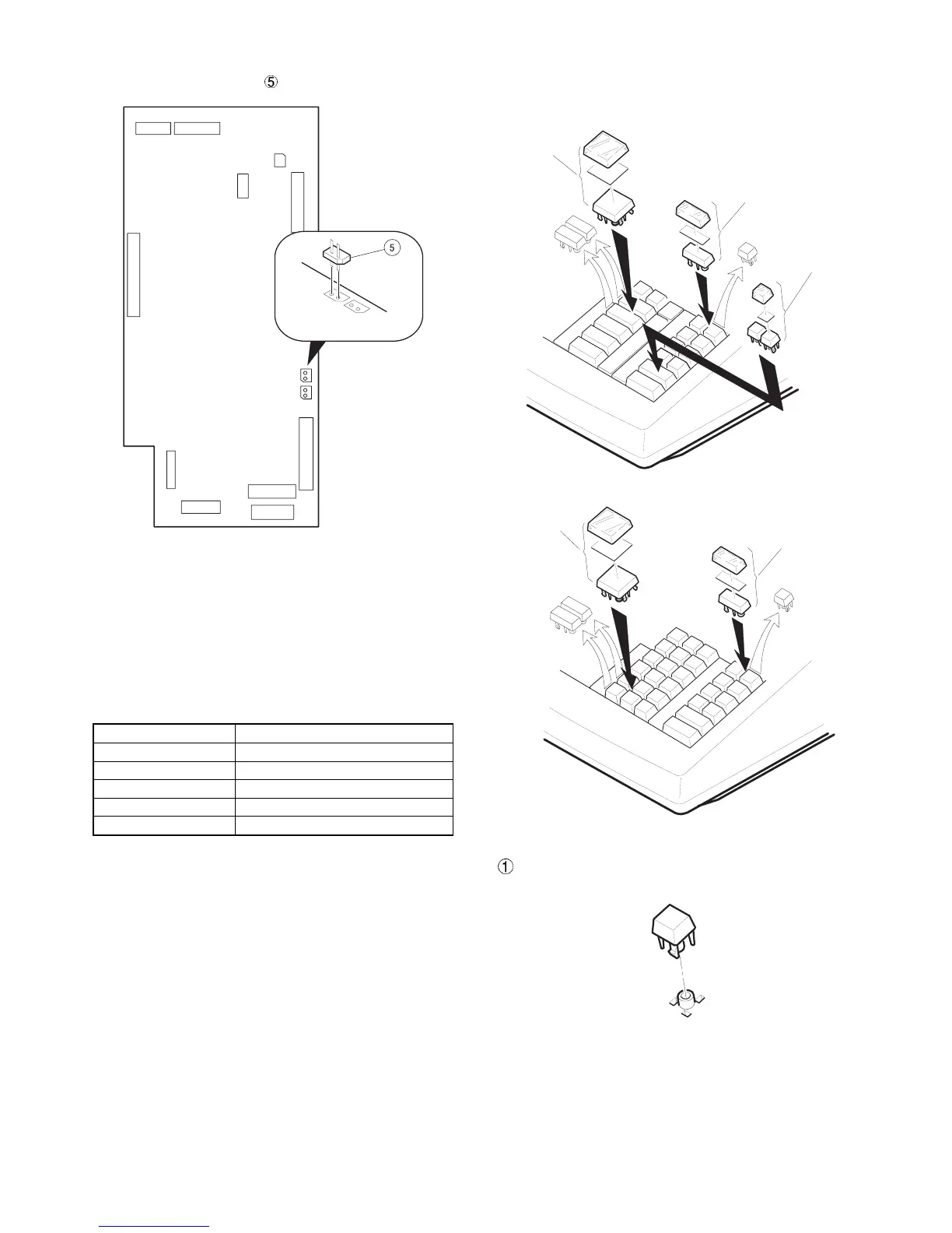
CHAPTER 9. KEY TOP KIT
1. Outline
The ER-A440 employs the following key top (option) to allow addi-
tional installation of the key top and change in the key layout.
MODEL NAME DESCRIPTION
ER-11KT7 1 × 1 Key top
ER-12KT7 1 × 2 Key top
ER-22KT7 2 × 2 Key top
ER-11DK7G 1 × 1 Dummy key
ER-51DK7G 5 × 1 Dummy key
2. Installation procedure
ER-11KT7
Solder the connector(2pin).
ER-22KT7
ER-12KT7
ER-11KT7
ER-22KT7
ER-12KT7
– 6 –