DISASSEMBLY
Caution:
Prior to the disassembly, be sure to remove the AC power
supply
cord,
cassette
tape
and
batteries
from
the
unit.
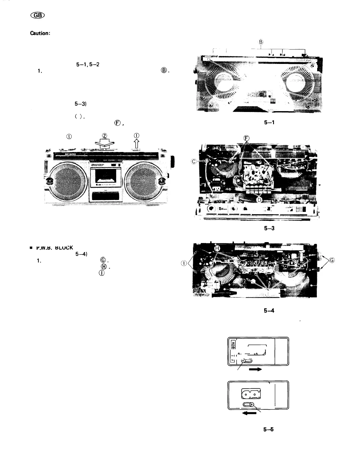
• FRONT CABINET REMOVAL
(Refer
to
Figures
5-1,5-2
and
5-3)
1.
Remove the eight screws ® and the six knobs
(g).
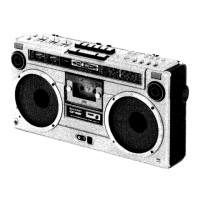
2. Push the stop/eject Button to open the cassette holder.
3. Pull the front cabinet frontward by holding its upper
part and disconnect the speaker socket © .
• MECHANISM BLOCK REMOVAL
(Refer to Figure
5—3)
1. Remove the two screws © and the Digital Tape
Counter Belt
(
).
2. Disconnect the three sockets
(f),
then the mechanism
block can be removed.
Q
&
?
jfci
*±Е
ав
***
""SJS?
°^®$9?
>
2&3
&^^'
:
*"
---^ru:
"
Угли.
.«Я*^
«jamj^iisBjMMeM^eeliHsiiMJB^^^^^^^^^^^^^^^^^^^^^^^^^^^^^^^^^^™
Чв&
Figure
5—1
I
Figure 5-2
Figure
5-3
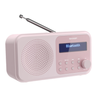
P.W.B.
BLUCK
REMOVAL
(Refer to Figure
5—4)
1.
Remove the two knobs
(§
2. Disconnect the two tips
(J
3. Remove the six screws
<X
, then amp. and tuner P.W.B.
can be removed from the back cabinet.
.'яаркйг
Figure
5—4
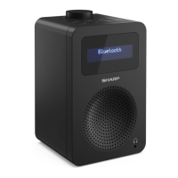
VOLTAGE SELECTION
Before operating the unit on mains, check the preset voltage.
If the voltage is different from your local voltage, adjust the
voltage as follows: Slide the AC power supply socket cover
by a
little
loosing
screw
to the
visible
indication
of the
side
of your local voltage. See Figure 5-5.
|i|
,,
' о о
о
ni
—
,
л
^
о
^
^
Screw
5
I
^^^
Screw
Figure
5-5
-5-