MECHANICAL ADJUSTMENT
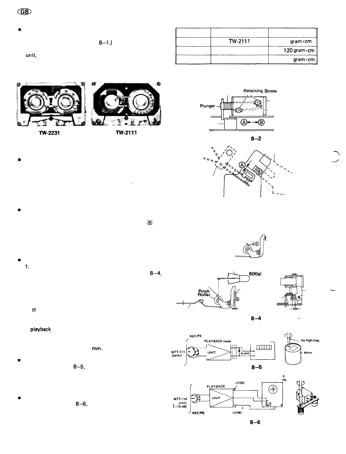
TORQUE CHECK AT PLAY, FAST FORWARD AND
REWIND MODES
(Refer to Table 8-1 and Figure
8-1.)
Put a torque meter cassette in the cassette holder of the
unit,
and see
that
the
measured
torque
in
each
mode
is
normal as follows.
Mode
Play back
Fast-forward
Rewind
Torque meter cassette
TW-2111
TW-2231
TW-2231
Measured torque
35 ~ 60 gram
-cm
85 ~
120
gram
-cm
85 ~ 120 gram
-cm
Table 8-1
TW-2231
TW-2111
Figure 8-1
POSITIONAL ADJUSTMENT OF PLUNGER AND
SOLENOID
(Refer to Figure 8-2)
If the attractive stroke of the plunger is insufficient, adjust
it by shifting the solenoid in the direction (g) . If the at-
tractive force of the solenoid is insufficient, adjust it by
shifting the solenoid in the direction ® .
TIMING ADJUSTMENT OF APSS SWITCH
(Refer to Figure 8-3)
While the unit is in playback mode, bend the part
(B)
of
the sub chassis back lever to such degree that the clearance
® between the APSS switch and the sub chassis back
lever becomes about 1 mm. And check that the APSS
switch is turned on when the unit gets in APSS mode.
PINCH ROLLER PRESSURE CHECK
1.
Place the unit in playback mode.
2. Push the pinch roller, at the point shown in Figure
8—4,
by using a tension gauge (500 g) so that it will come off
the
capstan.
Then,
slowly
release
the
tension
until
the
pinch roller hits the capstan again (i.e., the pinch roller is
about to rotate again). Check, then, the tension gauge is
reading 270 g to 370 g.
3.
If
the reading is outside the range of 270 g to 370 g,
replace the pressure spring of the pinch roller.
Notes:
In
playback
mode, make sure that the clearance (g) and the
clearance (g) are more than 0.2 mm and more than 0.1 mm
respectively. Next in pause mode, make sure that the
clearance © is more than 0.3
mm.
TAPE SPEED ADJUSTMENT
As shown in Figure
8—5,
make connection of instrument,
put a screwdriver (for high-frequency use) into the hole of
the motor, and adjust the variable resistor so that the
output frequency is 2960 to 2985 Hz on frequency counter.
RECORD/PLAYBACK HEAD AZIMUTH ADJUSTMENT
As shown in Figure
8—6,
make connection of instrument,
and adjust the head azimuth adjusting screw so that the
output signals from both channels will have maximum
waveform with the same phase in right and left.
Spring
Retaining
Screw
Plunger—I
APSS Release
Lever
Solenoid
Attractive Stroke
Figure
8—2
Sub Chassis
Back Lever
APSS
Switch
Figure 8-3
Tension Gauge
(500g)
Capstan
^D'
Pause
Lever
Sub Chassis
Pinch Roller
Pressure Spring
-Pinch
Roller
Figure
8-4
EXT.
SP
REC/PB
(J10S. 106) FREQUENCY
Л
HEAD
PLAYBACK
mode
/ COUNTER
TEST TAPE
MTT-111
13kHz)
^S-
Figure
8-5
Screwdriver
for
high-freq.
use
TEST TAPE
MTT-114
/10
kHz\
(-10dB)
REC/PB
HEAD
EXT.
SP
IJ105)
LAYBACK
mode
,
GROUND
L_
I
——————
I
\
I
———
IJ106)
EXT.
SP
DUAL TRAC
SYNCROSCO
Ф
]
i i
о
4
сн°
Т си
2
Figure
8—6
-8-