GX-CD5100W
7 – 4
The RF waveform is normal and the time is dis-
played normally, but no sound is produced. Or the
sound has dropouts.
(4) PLL system check.
When a disc is loaded, start play operation.
The RF waveform is normal, but the TOC data cannot be read.
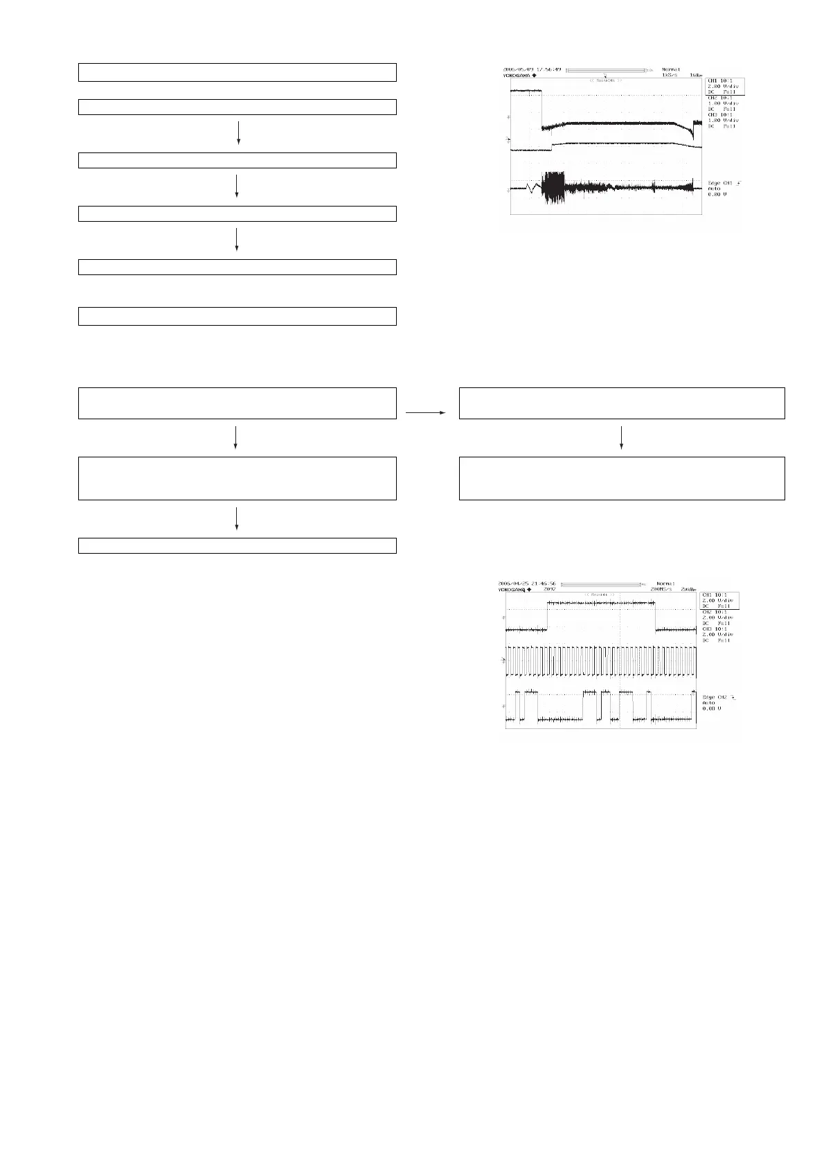
Check the PDOUT waveform. (Figure 6)
Check around pins 26~30 on IC1.
Figure 6
PDOUT 0
PDOUT 1
FDO
(5) Others.
Is pin 35 (C2F) on IC1 "L" ? No There are too many error flags on a damaged disc which makes
error correction impossible.
Yes
1. When playing at normal speed.
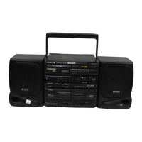
Check the peripheral circuit at pin 58 ~ 60 (DOUT) on IC1 and
the waveform (Figure 7).
Check again using a known good disc.
If OK, Check the unit.
Figure 7
LRSY
DATACK
DATA