HT-SL50
6 – 1
CHAPTER 6. CIRCUIT SCHEMATICS AND PARTS LAYOUT
[1] Notes On Schematic Diagram
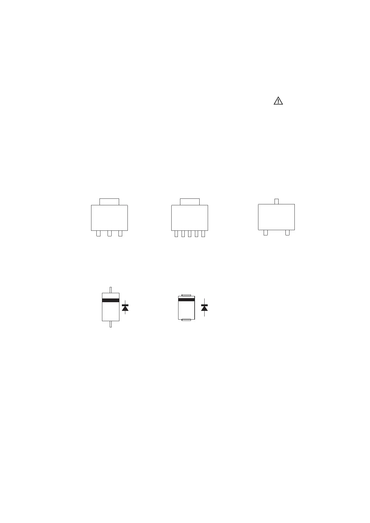
[2] Types Of Transistor And LED
••
•
Resistor:
To differentiate the units of resistors, such symbol as
K and M are used: the symbol K means 1000 ohm
and the symbol M means 1000 kohm and the
resistor without any symbol is ohm-type resistor.
Besides, the one with “Fusible” is a fuse type.
Capacitor:
To indicate the unit of capacitor,
a symbol P is used:
this symbol P means pico-farad and the unit of the
capacitor without such a symbol is microfarad. As to
electrolytic capacitor, the expression “capacitance/
withstand voltage” is used.
(CH), (TH), (RH), (UJ): Temperature compensation
(ML): Mylar type
(P.P.): Polypropylene type
Schematic diagram and Wiring Side of P.W.Board
for this model are subject to change for
improvement without prior notice.
•
•
The indicated voltage in each section is the one
measured by Digital Multimeter between such a
section and the chassis with no signal given.
Parts marked with “ ” are important for
maintaining the safety of the set. Be sure to replace
these parts with specified ones for maintaining the
safety and performance of the set.
1117Y33
(1) (2) (3)
(1) (2) (3)(4) (5)
TOP VIEW
TOP VIEW
NM3421
WEIV POTWEIV POT
1N4004
TOP VIEW
DXA010
KRC104S
B
(3)
E
(1)
C
(2)