– 41 –
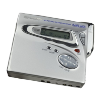
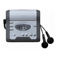
IM-MT899H/IM-MT899W
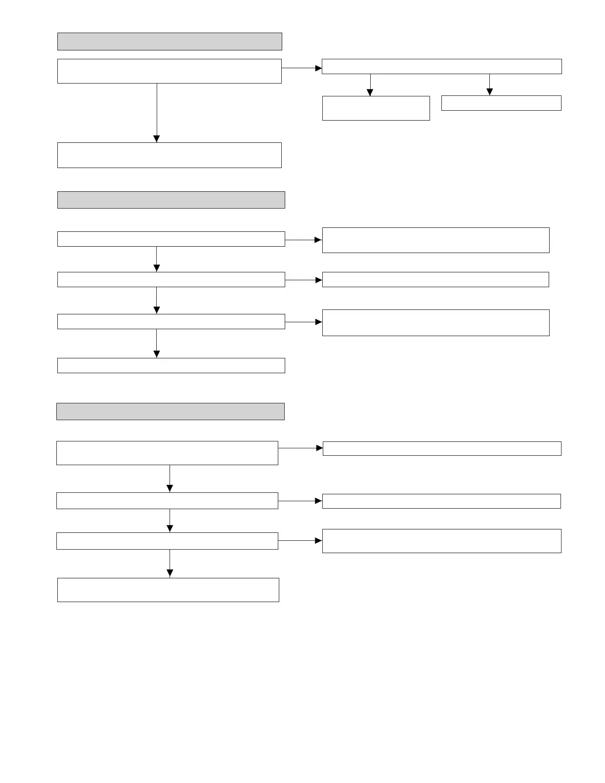
Yes
Check for defective solder joint of audio signal line between
IC703 and J703.
No
Yes
Is audio waveform output from J703 pins 3 and 4 ?
Check pins 4 and 21 of IC703 and pins 15 and 16 of IC501.
No
Yes
Is audio waveform output from IC703 pins 8 and 17 ?
Check pins 70 to 72 and 74 of IC201, and pins 9 to 12 of
IC501.
No
• Abnormal display
No
Yes
Are the pin 2 (VCC) and pin 12 (GND) normal ?
Is waveform output from pins 2, 54 and 58 of IC401 ?Is waveform output from CN451 pins 3 to 5 ?
Yes
Check between IC401 and
CN451.
No
Check the periphery of IC401.
• Audio playback clrcult
Is audio waveform output from IC501 pins 15 and 16 ?
Check headphones jack, and periphery of headphone.
In the normal playback mode, LCD play time display functions, but no audio is heard.
Check for pattern breakage of flexible PWB, check for
defects of display microcomputer (replace the display unit).
• The spindle motor does not rotate.
No
Does the waveform appear on the IC201 pins 24 and 25 after
TEST mode AUTO2 completion and in this state ?
Check the periphery of IC201.
Yes
Does waveform appear on the IC601 pins 28 and 33 ?
Does waveform appear on IC601 pins 57, 59 and 61 ?
Check the soldering of CN601 and the flexible PWB, or
replace the spindle motor.
Yes
No
If the waveform is not observed after resoldering of C601,
replace it.
No
Check the periphery of IC601.
Yes