– 28 –
IM-MT899H/IM-MT899W
SW401 EJECT OFF—ON
SW402 OPEN/CLOSE OFF—ON
SW901 DISC PROTECT OFF—ON
SWA01 RECORD OFF—ON
SWA02 PLAY OFF—ON
SWA03 STOP OFF—ON
SWA04 SKIP UP OFF—ON
SWA05 SKIP DOWN OFF—ON
SWA06 VOLUME + OFF—ON
SWA07 VOLUME – OFF—ON
SWA08 MODE OFF—ON
SWA09 SYNCHRONISED RECORDING OFF—ON
NOTES ON SCHEMATIC DIAGRAM
• Resistor:
To differentiate the units of resistors, such symbol as K and
M are used: the symbol K means 1000 ohm and the symbol
M means 1000 kohm and the resistor without any symbol is
ohm-type resistor. Besides, the one with “Fusible” is a fuse
type.
• Capacitor:
To indicate the unit of capacitor, a symbol P is used: this
symbol P means pico-farad and the unit of the capacitor
without such a symbol is microfarad. As to electrolytic
capacitor, the expression “capacitance/withstand voltage” is
used.
(CH), (TH), (RH), (UJ): Temperature compensation
(ML): Mylar type
• The indicated voltage in each section is the one measured
by Digital Multimeter between such a section and the chas-
sis with no signal given.
• Parts marked with “ ” ( ) are important for
maintaining the safety of the set. Be sure to replace these
parts with specified ones for maintaining the safety and
performance of the set.
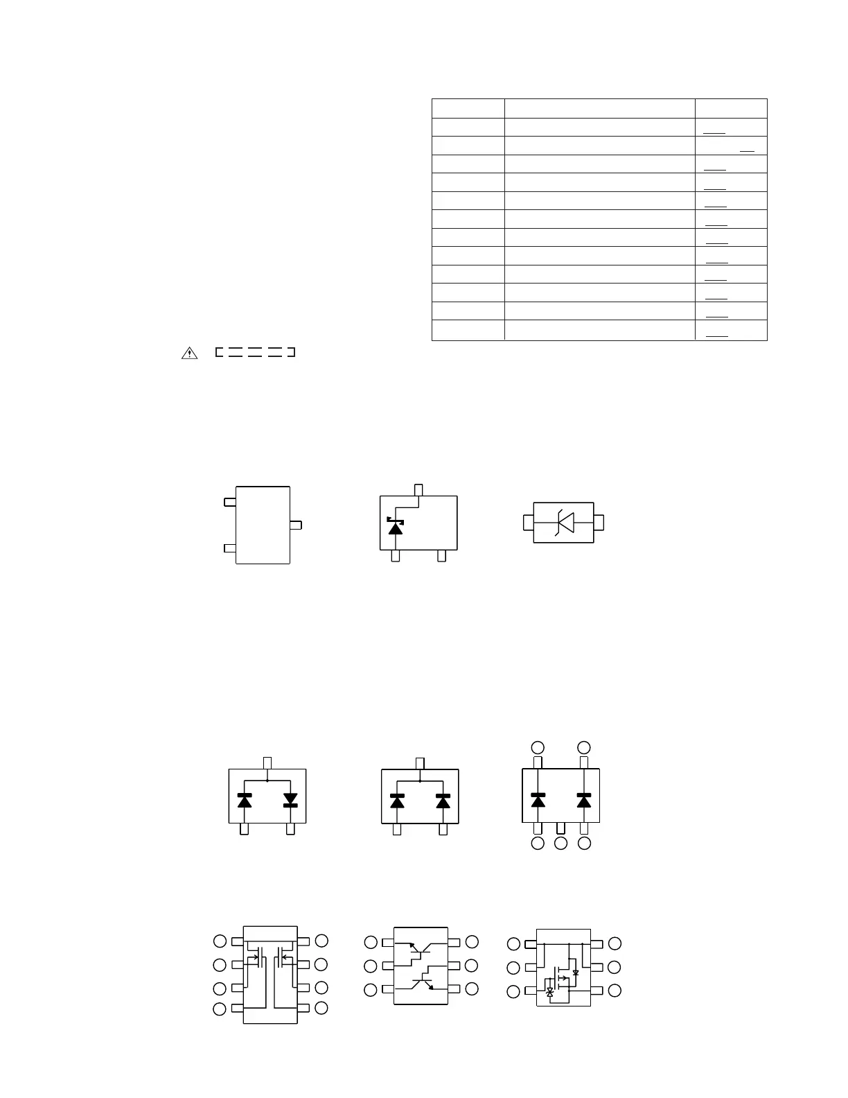
POSITION
REF. NO
DESCRIPTION
2SA17457
2SB1462 J
2SC4617 R
2SD2351 W
MCH3409
RT1N441 U
015Z5.1Y
15AZ6.2Y
15AZ7.5Y
RB520S30
MA8075M
1SS388
1SS389
FS1J2EA
TOP
VIEW
F10J2E
TOP VIEW
B
(G)
(2)
E
(S)
1
C
(D)
(3)
SBE803
TOP VIEW
MA132WK
1SS302
TOP VIEW
SSM6J08FU
TOP VIEW
1
12
3 4 5
2
3
4
5
6
HRB0103B
1SS372
TOP VIEW
XP04313
XP04501
TOP VIEW
1
2
3
4
5
6
1
2
3
6
7
8
4
5
FTD2017
D1
S1
S1
G1
D2
S2
S2
G2
TYPES OF TRANSISTOR AND DIODE