23
KB-6525PS
KB-6525PK
KB-6525PW
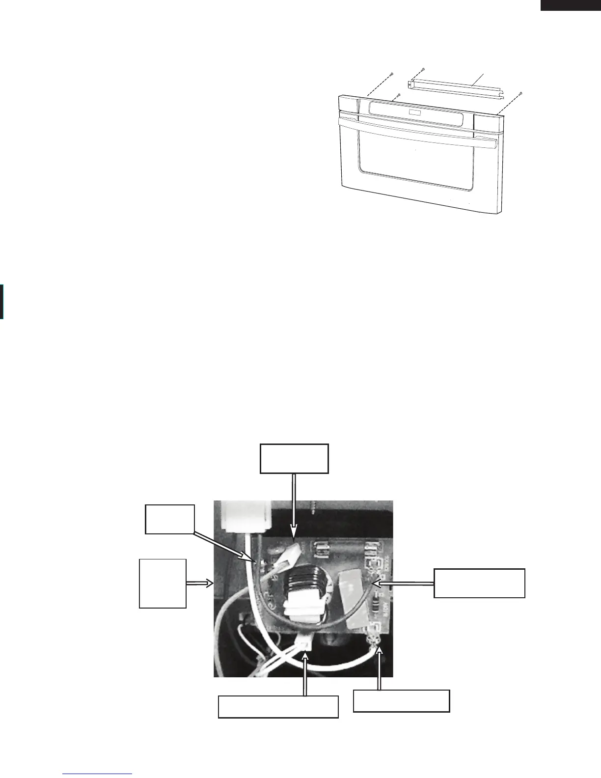
6. To remove the Control Panel Frame Assembly,
remove the (1) screw holding the C/P cover, then unplug
Control panel harness. Remove the (3) screws holding
the Control Panel frame to faceplate (Fig 3).
7. After the Control panel frame is removed, you now have
access to the CPU board.
Fig. 3
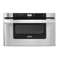
NOISE FILTER BOARD REPLACEMENT
1. Un-hook the black and white AC terminals from the Noise Filter PWB, plus the Red and double White terminals
(Fig 4).
2. Remove the (1) screw holding the Noise Filter (Fig 4).
Fig. 4
3. Reverse order to reinstall.
Noise
Filter
Unit
Red Wire
Double White Wire
White AC Wire
Black AC Wire
Screw