9
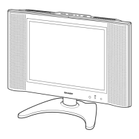
LC-13B4E
LC-15B4E
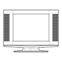
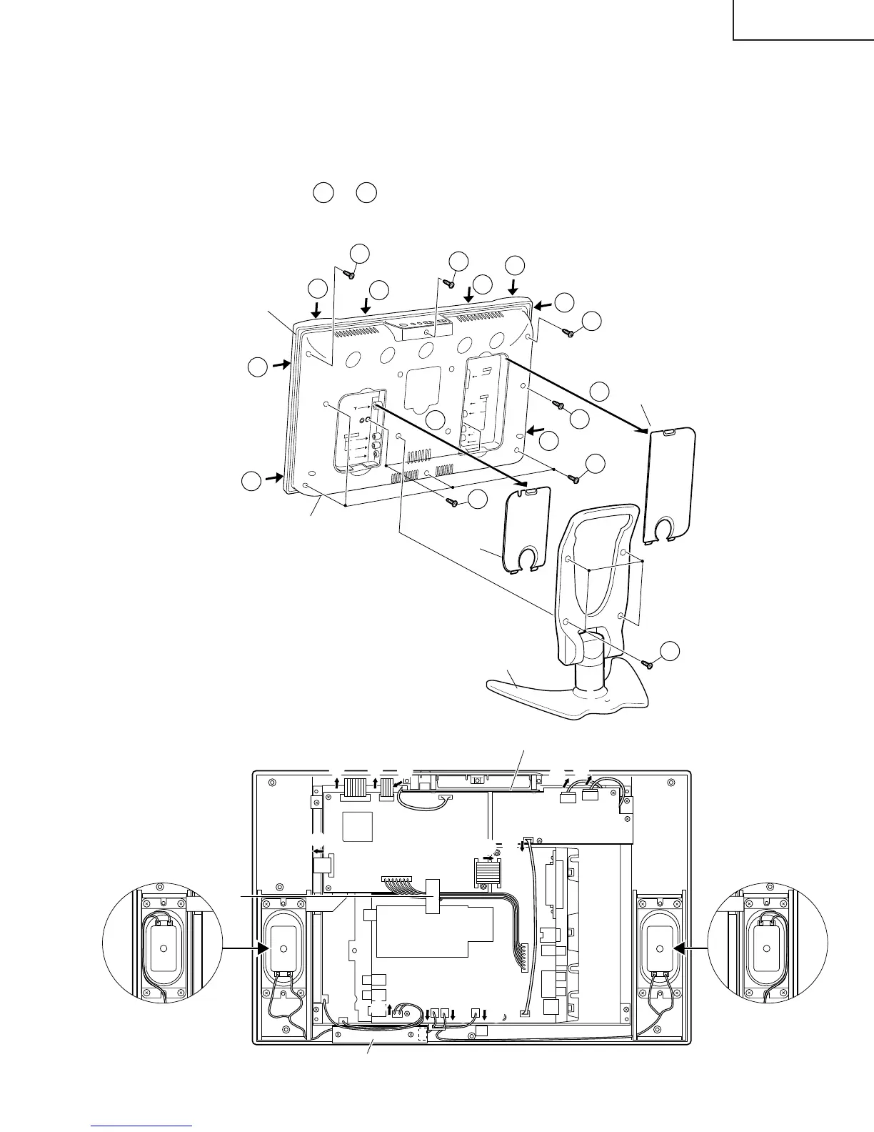
REMOVING OF MAJOR PARTS
1. Remove the stand fixing screws (4 pcs.).
2. Remove the two terminal covers.
3. Remove the terminal section fixing screws (2 pcs.).
4. Remove the cabinet B fixing screws (8 pcs.).
5. Cabinet A is opened order of
5-1
to
5-8
, and detach the Cabinet B.
6. Peel off the tape.
7. Detach the connector from each PWB.
L
R
A
U
D
I
O
O
U
T
RG
B
A
V
-
I
N
1
S-V
ID
E
O
V
I
D
E
O
P
O
W
E
R
I
N
P
U
T
D
C
1
2V
L
R
A
U
D
I
O
A
V
-
I
N
2
4
Cabinet A
Cabinet B
Stand
Terminal
cover (S)
Terminal
cover (L)
3
4
1
4
4
5-2
5-1
5-7
5-6
5-5
5-4
5-3
5-8
4
2
2
7
7
7
7
7
7
7
6
7
7
7
7 7
7
OPERATION PWB
MAIN PWB
TUNER PWB
INVERTER PWB
LED PWB
P4004 P2001
P6500
P6502
P3603
P6501
SC1204
SC1202SC1203
SC3902
SC2002
P3302 P3301 P3902
P1902
P701
P3601
Tape
Only for LC-13B4E Only for LC-13B4E