9
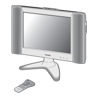
LC-20E1H
LC-20E1M
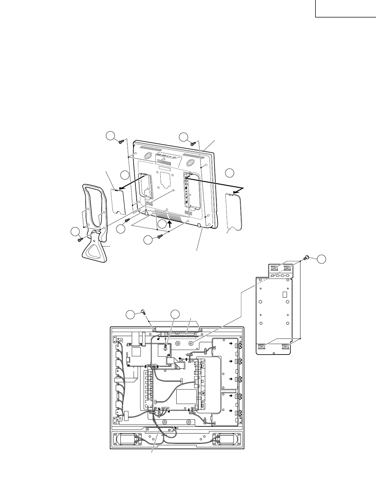
REMOVING OF MAJOR PARTS
1. Remove the table stand fixing screws (4 pcs.).
2. Remove the two terminal covers.
3. Remove the terminal section fixing screws (2 pcs.).
4. Remove the cabinet B fixing screws (10 pcs.).
5. Remove the cabinet B after opening from the direction of an arrow.
6. Remove the reinforcement angle fixing screws (4 pcs.).
7. Remove the top cover fixing screws (2 pcs.).
8. Remove the control PWB fixing screws (2 pcs.).
9. Detach the connector from each PWB.
3
4
4
4
2
2
5
1
Cabinet A
Cabinet B
Stand
Terminal
Cover (S)
Terminal
Cover (L)
Reinforcement
Angle
Inverter-A
PWB
Inverter-B
PWB
R/C, LED PWB
Control PWB
Analog
PWB
Digital
Digital
PWB
P6705
P3703
SC1201SC1202
SC1202
P4004
P4004
SC1203
P2004
SC2001
SC3403
P3702
P6706
P3704
P3602
P3602
P3601
P2003
P6705
SC1203
SC2001
SC3403
P6706
P3704
9
9
9
9
9
9
9
9
9
9
9
9
6
P3500
P3500
P3503
P3504
P3504
7
8