EasyManua.ls Logo

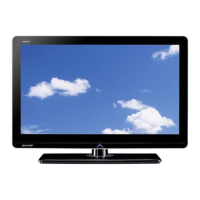
Sharp LC-24LE170I

Sharp LC-24LE170I
54 pages
To Next Page IconTo Next Page
Loading...
SERVICE MANUAL
Parts marked with " " are important for maintaining the safety of the set. Be sure to replace these parts with specified ones for maintaining the
safety and performance of the set.
This document has been published to be used for
after sales service only.
The contents are subject to change without notice.
SAFETY PRECAUTION
IMPORTANT SERVICE SAFETY PRE-
CAUTION ............................................................i
PRECAUTIONS FOR USING LEAD-FREE
SOLDER ............................................................ii
CHAPTER 1. OUTLINE
[1] OUTLINE ...................................................... 1-1
........ 7-1
........ 8-1
........ 9-1
........ 9-5
........ 9-7
CHAPTER 2. SPECIFICATIONS
[1] SPECIFICATION .......................................... 2-1
CHAPTER 3. OPERATION MANUAL
[1] OPERATION MANUAL ................................ 3-1
CHAPTER 4. DIMENSIONS
[1] DIMENSIONS .............................................. 4-1
CHAPTER 5. REMOVING MAJOR PARTS
[1] REMOVING OF MAJOR PARTS ........................ 5-1
CHAPTER 6. ADJUSTMENT
[1
] ADJUSTMENT ............................................. 6-1
CHAPTER 7. TROUBLE SHOOTING TABLE
[1] TROUBLE SHOOTING TABLE.............
CHAPTER 8. OVERALL WIRING/SYSTEM BLOCK
DIAGRAM
[1] SYSTEM BLOCK DIAGRAM................
CHAPTER 9. PRINTED WIRING BOARD
ASSEMBLIES
[1] MAIN UNIT............................................
[2] LED RC UNIT.......................................
[3] POWER UNIT.......................................
..... 10-1
..... 10-4
...... 10-2
...... 10-6
CHAPTER 10. SCHEMATIC DIAGRAM
[1] DESCRIPTION OF SCHEMATIC
DIAGRAM..............................................
[2] MAIN UNIT ...........................................
[3] LED RC UNIT .......................................
[4] POWER UNIT ......................................
Parts Guide
TopPage
LC-24LE170I
CONTENTS
LED BACKLIGHT TV
LC-24LE170I
MODEL
In the interests of user-safety (Required by safety regulations in some countries) the set should be restored to its orig-
inal condition and only parts identical to those specified should be used.
Question and Answer IconNeed help?

Do you have a question about the Sharp LC-24LE170I and is the answer not in the manual?

Sharp LC-24LE170I Specifications

General IconGeneral
Screen Size24 inches
Resolution1366 x 768
Display TypeLED
HDMI Ports2
USB Ports1
Weight5.2 kg
Aspect Ratio16:9
Refresh Rate50 Hz
Sound Output10 W
Backlight TypeLED

Summary

Safety Precautions

Important Service Safety Precaution

Critical safety measures for technicians during service.

Before Returning the Receiver (Fire & Shock Hazard)

Post-service safety checks to prevent fire and shock hazards.

Safety Notice

General safety advice regarding part replacement and characteristics.

Precautions for Using Lead-Free Solder

Detailed instructions on using lead-free solder and its implications.

Chapter 1: Outline

[1] Outline

General overview of the TV's design and purpose.

Chapter 2: Specifications

[1] Specifications

Detailed technical specifications of the LC-24LE1701 model.

Chapter 3: Operation Manual

[1] Operation Manual

Instructions for using the TV's features and functions.

Remote Control Unit

Description and function of each button on the remote control.

Attaching the Stand

Attaching the Stand

Step-by-step guide for assembling the TV stand.

Chapter 4: Dimensions

[1] Dimensions

Physical measurements and mounting information for the TV.

Chapter 5: Removing Major Parts

[1] Removing of Major Parts

Procedures for disassembling and removing key internal components.

1. Removing Speaker LR and PWB Chassis.

Steps to remove speakers and the main Printed Wiring Board assembly.

1. Removing of the LCD Panel Module

Procedures for safely removing the LCD panel module from the TV.

Chapter 6: Adjustment

[1] Adjustment Procedure

Steps to enter and navigate the TV's adjustment mode.

3. Software Upgrading

Process for updating the TV's firmware via USB.

1. Signal Adjustment

Procedures for calibrating signal inputs for optimal picture quality.

B. White Balance Adjustment

Detailed procedure for white balance calibration.

Chapter 7: Troubleshooting Table

[1] Troubleshooting Table

Diagnostic guide for identifying and resolving common TV issues.

Chapter 8: Overall Wiring System Block Diagram

[1] System Block Diagram

High-level overview of the TV's functional blocks and interconnections.

Chapter 9: Printed Wiring Board Assemblies

[1] Main & Power Unit

Component layout and identification for the Main & Power PWB.

[2] LED RC Unit

Component layout and identification for the LED RC PWB.

Chapter 10: Schematic Diagram

[1] Description of Schematic Diagram

Explanation of schematic symbols and measurement conditions.

[2] Main Unit

Detailed electrical schematic for the main circuit board.

[3] LED RC Unit

Detailed electrical schematic for the LED RC circuit board.

[4] POWER Unit

Detailed electrical schematic for the power supply circuit board.

SHARP PARTS GUIDE

[1] PRINTED WIRING BOARD ASSEMBLIES

Part numbers and descriptions for PWBs.

[3] MAINPOWER UNIT

Part numbers and descriptions for the Main/Power unit components.

Related product manuals