DISASSEMBLY INSTRUCTIONS
B1-2
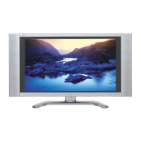
Fig. 1-5
1-5: DIGITAL PCB/ MAIN PCB (Refer to Fig. 1-5)
1.
2.
3.
4.
5.
6.
7.
8.
9.
10.
11.
12.
13.
14.
15.
Remove the 4 screws 1.
Remove the 6 screws 2.
Remove the Plate Jack in the direction of arrow (A).
Disconnect the following connector:
(CP3400).
Remove the 4 screws 3.
Remove the 2 screws 4.
Remove the Shield Digital and Fan Motor in the direc-
tion of arrow (B) and (C).
Disconnect the following connector:
(CP6401).
Remove the 4 screws 5.
Remove the Digital PCB in the direction of arrow (D).
Remove the 4 screws 6.
Remove the Shield Scaler in the direction of arrow (E).
Disconnect the following connector:
(CP3801, CP3802, CP4301, CP4305 and CP7201).
Remove the 3 screws 7.
Remove the Main PCB in the direction of arrow (F).
1-6: POWER PCB (Refer to Fig. 1-6)
1.
2.
Remove the 8 screws 1.
Remove the Power PCB in the direction of arrow.
Fig. 1-6
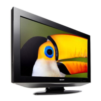
1-7: COVER LCD (Refer to Fig. 1-7)
1.
2.
Remove the 4 screws 1.
Remove the Cover LCD in the direction of arrow.
1
Cover LCD
Fig. 1-7
1
1
1
LCD Panel
(B)
(A)
1
2
Digital PCB
2
5
Plate Jack
Shield Digital
4
3
Power PCB
1
1
1
1
1
1
1
1
(D)
(E)
(F)
Fan Motor
4
3
3
3
5
5
5
(C)
6
6
6
6
7
7
7
Shield Scaler
Main PCB
1
2