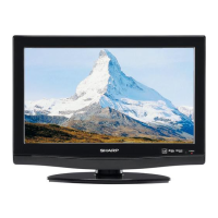
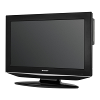
DISASSEMBLY INSTRUCTIONS
B1-2
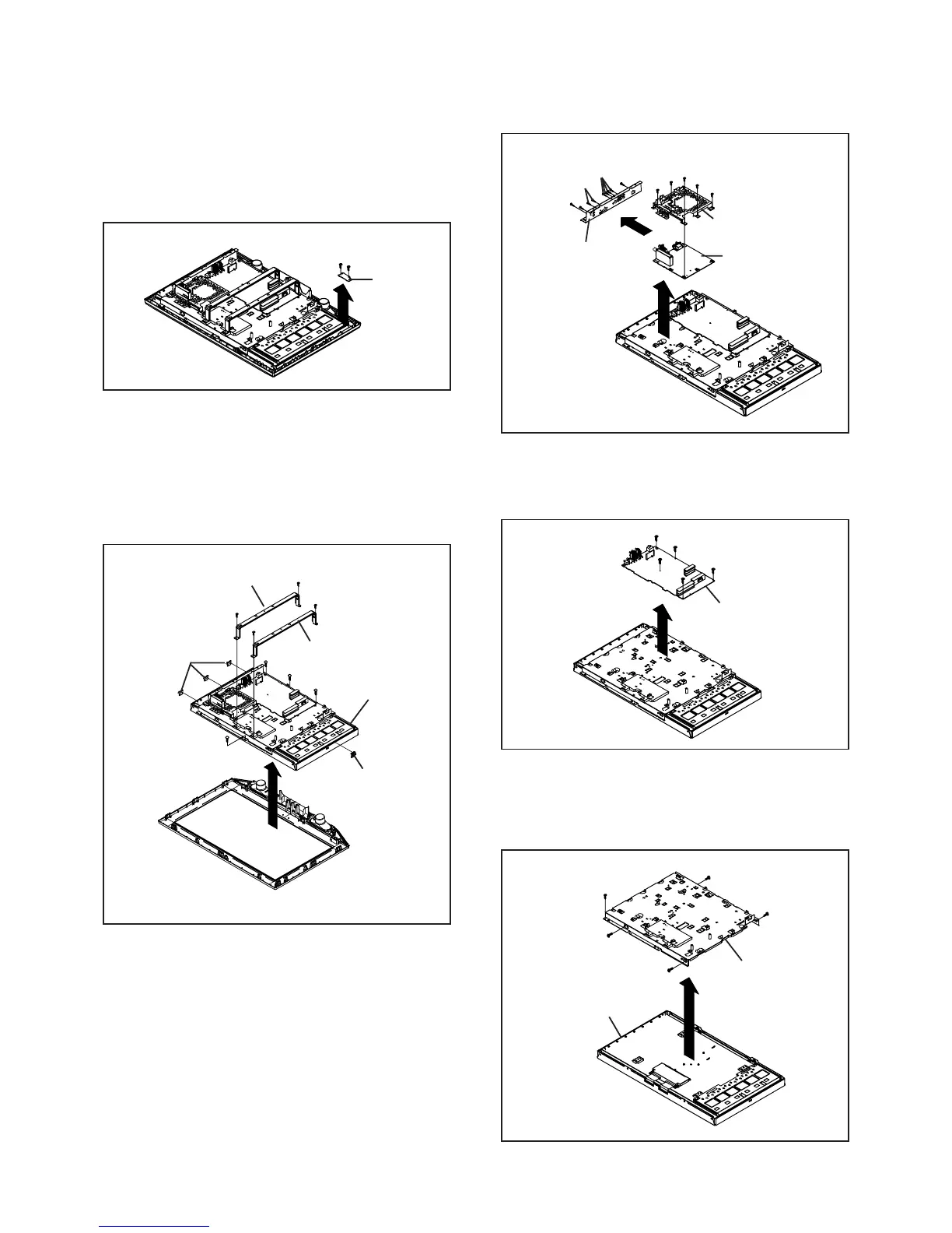
Fig. 1-6
1-7: POWER PCB (Refer to Fig. 1-7)
1.
2.
Remove the 5 screws (1).
Remove the Power PCB in the direction of arrow.
Fig. 1-7
(B)
(A)
(1)
(2)
Digital PCB
Power PCB
(1)
1-8: COVER LCD (Refer to Fig. 1-8)
1.
2.
3.
Remove the 4 screws (1).
Remove the screw (2).
Remove the Cover LCD in the direction of arrow.
(1)
Cover LCD
Fig. 1-8
(2)
(3)
Plate Jack
Shield Digital
(4)
(5)
(1)
(1)
(1)
(1)
(1)
(1)
(1)
(1)
LCD Panel
1-4: REMOCON PCB (Refer to Fig. 1-4)
1.
2.
3.
Disconnect the following connector:
(CP4201).
Remove the 2 screws (1).
Remove the Remocon PCB in the direction of arrow (A).
1-6: DIGITAL PCB (Refer to Fig. 1-6)
1.
2.
3.
4.
5.
6.
7.
8.
Disconnect the following connector:
(CP3001 and CP4302).
Remove the screw (1).
Remove the 5 screws (2).
Remove the 2 screws (3).
Remove the screw (4).
Remove the Plate Jack in the direction of arrow (A).
Remove the 5 screws (5).
Remove the Digital PCB and Shield Digital in the
direction of arrow (B).
1-5: LCD BLOCK (Refer to Fig. 1-5)
1.
2.
3.
4.
5.
6.
Disconnect the following connectors:
(CP302, CP2804 and CP4303).
Remove the Holder Panel.
Remove the 4 screws (1).
Remove the LCD Block in the direction of arrow (A).
Remove the 4 screws (2).
Remove the Angle Main.
Fig. 1-5
Fig. 1-4
Remocon PCB
(1)
(1)
(1)
(1)
(1)
LCD Block
Angle Main
(2)
(2)
(A)
(2)
(2)
Angle Main
(A)
(5)
(5)
(5)
(5)
(2)
Holder Panel
Holder Panel
(1)