DISASSEMBLY INSTRUCTIONS
B2-2
[ 24 pin FFC ]
When installing the FFC, fold it correctly and install it as
shown from Fig. 2-3-A to Fig. 2-3-B.
2-3: FFC WIRE HANDLING
1.
Do not make the folding lines except the specified
positions for the FFC.
1.
NOTE
Fig. 2-3-A
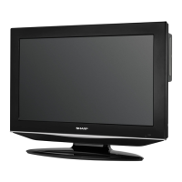
Traverse Ass'y
Check Hook
Check Hook
Check Hook
Fig. 2-2-E
• Loosen the wire in the direction of the arrow.
Check Hook
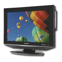
~ FEED MOTOR ~
WHITE (4)
BROWN (3)
~ SPINDLE MOTOR ~
YELLOW (2)
GREEN (1)
Fig. 2-2-D
Switch PCB Ass'y
• Install wire from (1) to (4) in order.
Fold
40 ± 1mm
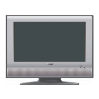
Fig. 2-2-C
8.0 ± 0.2mm
Safety surface for pressing
of the insert.
Feed Motor
Gear Motor
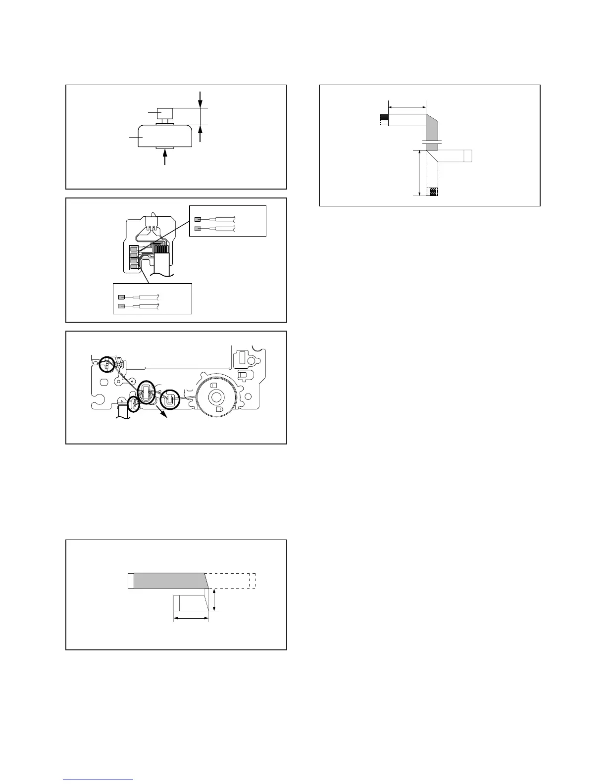
[ 6 pin FFC ]
Fig. 2-3-B
Fold
60 ± 1mm
Pick Up Side
Printing Surface
Fold it by 90˚
20 ± 1mm
Fold it by 90˚
30 ± 1mm