LC-32D65E/RU, LC-37D65E/RU
4 – 18
MONITOR ERR STBY table
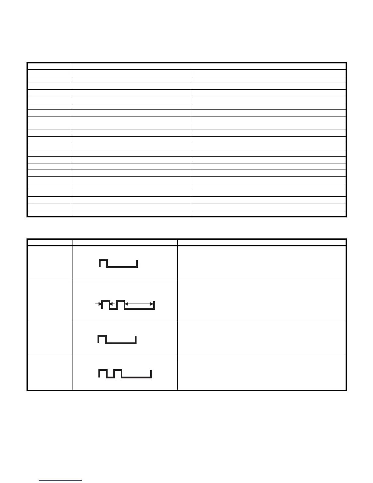
LED flashing timing chart at the time of the error
1) Power LED
Outline: Communication/Power failure detected by the monitor microprocessor (IC2003) is stored on EEPROM, and the last 4 abnormal
states can be confirmed in the adjustment process mode.
Location: Page 1/16 of the adjustment process mode: MONITOR ERR CAUSE
"0" if there is no error. It is cleared to 0 on the last page of the adjustment process mode.
Display Error description
02 Start-up communication error 2 Initial communication from the main CPU is not received.
03 Start-up communication error 3 Only the initial communication is received.
04 Start-up communication error 4 Until panel information request reception
05 Start-up communication error 5 Until initialization completion reception
06 Start-up communication error 6 Until version notification transmission
07 Start-up communication error 7 Until start-up information notification transmission
08 Start-up communication error 8 Until start-up information response reception
09 Start-up communication error 9 Until time-out setting reception
0A Communication error A REQ time-out
0B Communication error B Restart time-out during the beginning of time acquisition start-up
0C Communication error C Ending sequence time-out
0D Communication error D Preset start-up time-out during completion
0E Communication error E Download start-up time-out
0F Communication error F Time acquisition time-out
11 Communication error H Regular communication time-out
16 Panel-related error Lamp failure
1A Other error 2 Monitor temperature failure
1D Power supply error 1 PS_ON(AC_DET) failure
1E Power supply error 2 D_POW(DET_12V) failure
1F Power supply error 3 D_POW(DET_D3V3) failure
21 Power supply error 5 Panel power failure
23 Other error 3 Error standby request from the main CPU
Error type Power LED operation (1 cycle) Note: Pins are monitor microprocessor pins (IC2003).
Inverter/Lamp fail-
ure
Red flashes once
H: Red on Refer to "Inverter/Lamp failure details". OPC_LED flashes by pressing the
[MENU] key on the remote control.
L: Off
Power failure
Red flashes twice
H: Red on Refer to "Power failure details". OPC_LED flashes by pressing the [MENU]
key on the remote control.
L: Off
Communication
failure with main
CPU
Green flashes
once
H: Green on Refer to "Communication failure details". OPC_LED flashes by pressing the
[MENU] key on the remote control.
Communication line failure or main CPU communication failure.
L: Off
Others
Green flashes
twice
H: Green on Refer to "Other failure details". OPC_LED flashes by pressing the [MENU]
key on the remote control.
L: Off
300ms
1.5sec