LC-32DH57E-BK/RU-BK/S-BK
5 – 21
2.14. IC2701 (VHiYDA148QZ-1Y)
This IC is a block diagram and description LC-32A47E/RU/V (S59Z4LC32A47E) please see the service manual.
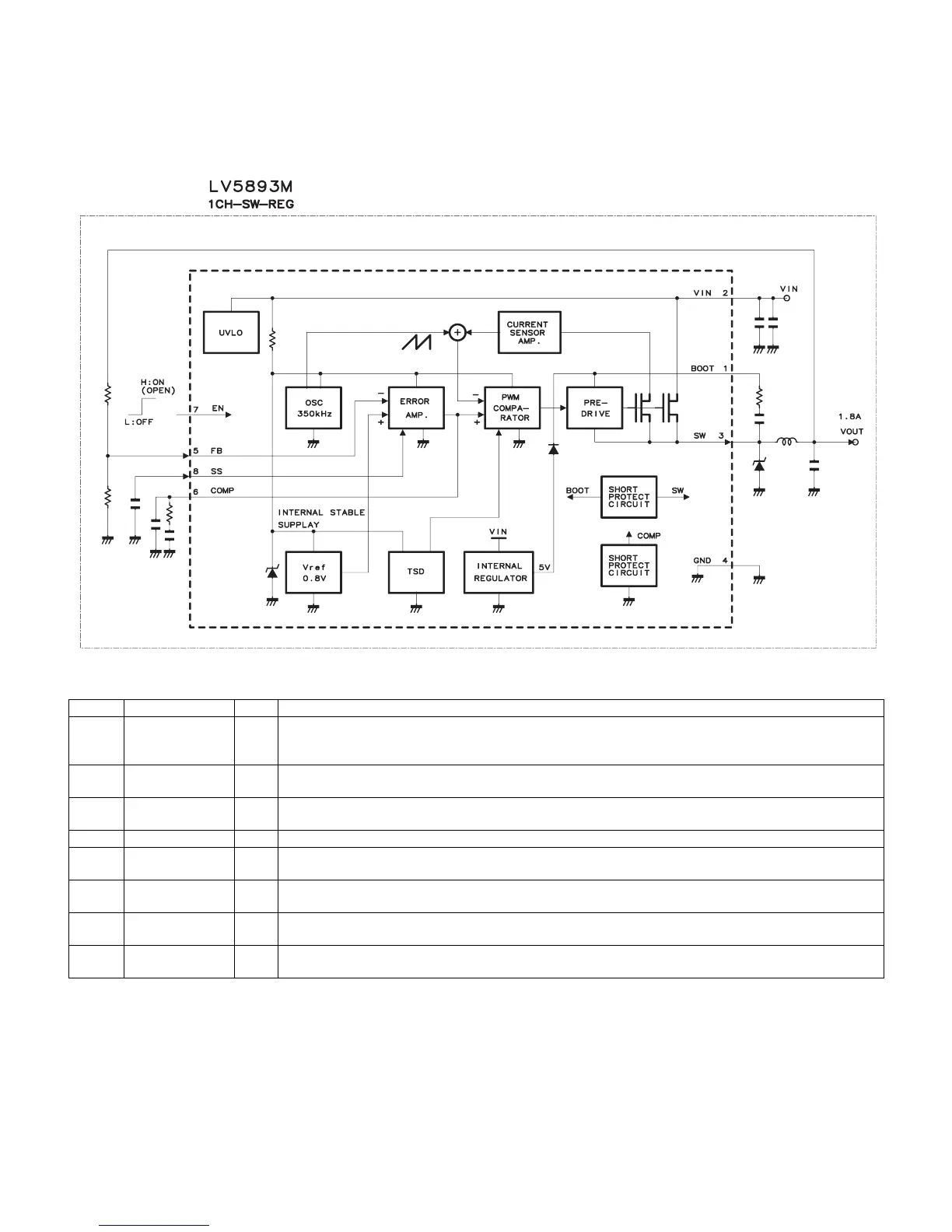
2.15. IC9605/IC9608 (VHiLV5893M+-1Y)
2.15.1 Block Diagram
2.15.2 Pin Connections and short description
2.16. IC9606 (VHiLV5805M+-1Y)
This IC is a block diagram and description LC-19D1E (S58J9LC19D1ES) please see the service manual.
Pin No. Pin Name I/O Pin Function
1 BOOT I Upper part MOS transistor boot strap capacity connection terminal.
Connect the boot capacity of about 0.022µF between SW terminals.
The boot capacity series resistance (about100Ω) is effective for stable operation.
2 VIN I Input power source terminal.
Connect very big capacity (10µF 2 or more) between GND.
3 SW I Power switch terminal.
Connect the output LC filter. Connect the above-mentioned capacity between BOOT terminals.
4 GND — Ground
5 FB I Feedback terminal.
The output voltage is set by the division resistance of output voltage (Vout-FB-GND).
6 COMP I Phase compensation terminal.
Connect external capacity and resistance for the phase compensation of the DC/DC converter close loop.
7 EN I Enable terminal
It operates the converter by a high voltage or the opening. It stops with GND the converter operation.
8 SS — Soft start terminal.
The soft start time is set by built-in 10µA source voltage and external soft start capacity.