EasyManua.ls Logo

Sharp LC-37D44U User Manual

Sharp LC-37D44U
113 pages
To Next Page IconTo Next Page
Page #1 background imageLoading...
Page #1 background image
SERVICE MANUAL
Parts marked with " " are important for maintaining the safety of the set. Be sure to replace these parts with specified ones for maintaining the
safety and performance of the set.
This document has been published to be used for
after sales service only.
The contents are subject to change without notice.
SAFETY PRECAUTION
IMPORTANT SERVICE SAFETY
PRECAUTION............................................................ i
PRECAUTIONS A PRENDRE LORS DE LA
REPARATION ........................................................... ii
PRECAUTIONS FOR USING LEAD-FREE
SOLDER ...................................................................iii
PRECAUTIONS IN SERVICING THE HDCP-
KEY ROM................................................................. iv
CHAPTER 1. SPECIFICATIONS
[1] SPECIFICATIONS .................................................1-1
CHAPTER 2. OPERATION MANUAL
[1] OPERATION MANUAL ..........................................2-1
CHAPTER 3. DIMENSIONS
[1] DIMENSIONS ........................................................3-1
CHAPTER 4. REMOVING OF MAJOR PARTS
[1] REMOVING OF MAJOR PARTS ...........................4-1
CHAPTER 5. ADJUSTMENT
[1] ADJUSTMENT PROCEDURE ...............................5-1
CHAPTER 6. TROUBLE SHOOTING TABLE
[1] TROUBLE SHOOTING TABLE..............................6-1
CHAPTER 7. MAJOR IC INFORMATIONS
[1] MAJOR IC INFORMATIONS..................................7-1
CHAPTER 8. OVERALL WIRING/BLOCK DIAGRAM
[1] OVERALL WIRING DIAGRAM ..............................8-1
[2] SYSTEM BLOCK DIAGRAM .................................8-2
CHAPTER 9. PRINTED WIRING BOARD ASSEMBLIES
[1] R/C, LED Unit.........................................................9-1
[2] KEY Unit.................................................................9-2
[3] MAIN Unit...............................................................9-3
CHAPTER 10. SCHEMATIC DIAGRAM
[1] DESCRIPTION OF SCHEMATIC DIAGRAM.......10-1
[2] R/C, LED Unit.......................................................10-2
[3] KEY Unit...............................................................10-3
[4] MAIN Unit.............................................................10-4
Parts Guide
TopPage
CONTENTS
In the interests of user-safety (Required by safety regulations in some countries) the set should
be restored to its original condition and only parts identical to those specified should be used.
LCD COLOR TELEVISION
No. S18D7LC37D44U
LC-37D44U
LC-37D44U
MODEL

Table of Contents

Question and Answer IconNeed help?

Do you have a question about the Sharp LC-37D44U and is the answer not in the manual?

Sharp LC-37D44U Specifications

General IconGeneral
BrandSharp
ModelLC-37D44U
CategoryLCD TV
LanguageEnglish

Summary

SAFETY PRECAUTION

IMPORTANT SERVICE SAFETY PRECAUTION

Key safety guidelines for service personnel, including warnings and cautions.

BEFORE RETURNING THE RECEIVER (Fire & Shock Hazard)

Essential safety checks required before returning the TV to the user.

SAFETY NOTICE

Information on safety-related characteristics of replacement parts.

PRECAUTIONS A PRENDRE LORS DE LA REPARATION

AVERTISSEMENT

General warnings and precautions for repair procedures.

VERIFICATIONS CONTRE L'INCEN-DIE ET LE CHOC ELECTRIQUE

Safety checks against fire and electric shock hazards.

AVIS POUR LA SECURITE

Importance of using identical replacement parts for safety.

PRECAUTIONS FOR USING LEAD-FREE SOLDER

Employing lead-free solder

Identification and use of lead-free solder.

Soldering

Guidelines and precautions for soldering with lead-free solder.

PRECAUTIONS IN SERVICING THE HDCP-KEY ROM

Information protection/management measures

Measures for protecting HDCP-KEY ROM information during servicing.

CHAPTER 1. SPECIFICATIONS

TV Specifications Overview

Detailed technical specifications of the LC-37D44U television.

CHAPTER 2. OPERATION MANUAL

Part Names and Controls

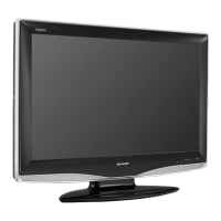
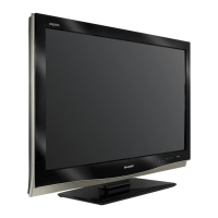
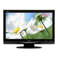
Identification of external parts and controls on the TV.

Remote Control Unit Functions

Detailed explanation of remote control buttons and their functions.

QUICK REFERENCE

Attaching and Detaching the Stand

Step-by-step guide for stand installation and removal.

Setting the TV on the Wall

Instructions and cautions for wall-mounting the television.

Troubleshooting Guide

Common TV Problems and Solutions

Troubleshooting common issues like no power, no picture, or no sound.

Digital Broadcasting Issues

Error messages and solutions for digital broadcast reception.

Environmental Usage Cautions

Precautions for operating the TV in high and low temperature environments.

CHAPTER 3. DIMENSIONS

TV Dimensions and Measurements

Physical dimensions of the LC-37D44U television in inches and mm.

CHAPTER 4. REMOVING OF MAJOR PARTS

Procedure for Major Part Removal

Step-by-step instructions for disassembling major TV components.

CHAPTER 5. ADJUSTMENT PROCEDURE

PWB and IC Replacement Notes

Important considerations after replacing internal circuit boards or ICs.

Microprocessor Software Upgrading

Process for upgrading firmware for main, monitor, and panel timing controllers.

Adjustment Process Mode Entry and Exit

Method to access and leave the service adjustment mode.

Remote Controller Operations in Adjustment Mode

Key operations and display descriptions during adjustment.

List of Adjustment Process Menus

Comprehensive list of adjustable parameters within the service menu.

Special Features: Standby Cause and EEP Save/Recover

Explanation of standby cause codes and EEPROM value management.

Code List for Standby Cause

Table of error codes indicating the cause of standby.

Signal Adjustment Procedures

Composite N358 Signal and Tuner Adjustment

Procedure for adjusting N358 signals and tuner input.

Component 15K Signal Adjustment

Procedure for adjusting component 15K video signals.

Component 33K Signal Adjustment

Procedure for adjusting component 33K video signals.

Analog RGB Signal Adjustment

Procedure for adjusting analog RGB input signals.

Tuner and V-Chip Test

Test procedures for the TV tuner and V-Chip functionality.

White Balance Adjustment

White Balance Adjustment Procedure

Detailed steps for calibrating white balance using specific settings.

Key Writing Procedures

Instructions for writing EDID data for analog RGB and HDMI inputs.

Adjustment Sequence for Gradation 6

Step-by-step sequence for G adjustment in gradation 6.

Factory Settings and Software Version

Restoring Factory Settings

Procedure to reset the TV to its original factory default settings.

Software Version Information

Details on main microprocessor, monitor, and EDID software versions.

CHAPTER 6. TROUBLE SHOOTING TABLE

Troubleshooting No Video Input

Diagnostic flowcharts for no video issues on various inputs.

Troubleshooting Composite and Component Video Issues

Flowcharts for diagnosing no video on composite and component inputs.

Troubleshooting S-Video and Digital Video Issues

Flowcharts for diagnosing no video on S-Video and LVDS/RSDS signals.

Troubleshooting Broadcast Signal Reception

Flowcharts for diagnosing no video from UHF/VHF and digital broadcasts.

Troubleshooting HDMI Input Video Issues

Flowcharts for diagnosing no video on HDMI inputs 4 and 5.

Troubleshooting PC Input Video Issues

Flowcharts for diagnosing no video on PC input 6.

Troubleshooting No Audio on Analog Inputs

Flowcharts for diagnosing no audio on analog input 1 and 2.

Troubleshooting No Audio on HDMI and PC Inputs

Flowcharts for diagnosing no audio on HDMI and PC analog inputs.

Troubleshooting Broadcast Audio Issues

Flowcharts for diagnosing no audio from UHF/VHF and digital broadcasts.

Troubleshooting Digital Audio Output Issues

Flowcharts for diagnosing no audio on the digital audio output.

Troubleshooting HDMI Audio Input Issues

Flowcharts for diagnosing no audio on HDMI inputs 4 and 5.

Troubleshooting Monitor Audio Output

Flowcharts for diagnosing no audio output from the monitor itself.

Power LED Flashing Indicators

Green Power LED Error Codes

Interpretation of green power LED flash patterns for error notification.

Power Failure LED Indicators

Details on power LED flashes indicating power supply failures.

Communication Failure LED Indicators

Details on LED flashes indicating communication failures.

CHAPTER 7. MAJOR IC INFORMATIONS

Key Integrated Circuits

Information on major ICs, including the system LSI (IC8001).

CHAPTER 8. OVERALL WIRING/BLOCK DIAGRAM

Overall Wiring Diagram

A diagram showing the interconnection of major TV components.

System Block Diagram

A functional block diagram illustrating the TV's internal system architecture.

CHAPTER 9. PRINTED WIRING BOARD ASSEMBLIES

R/C, LED Unit PWB Layout

Component layout diagram for the R/C and LED unit.

KEY Unit PWB Layout

Component layout diagram for the key input unit.

MAIN Unit PWB Layout (Side-A)

Component layout diagram for the main unit, side A.

CHAPTER 10. SCHEMATIC DIAGRAM

Schematic Diagram Description and Conventions

Explanation of schematic symbols, voltage measurement, and component notations.

R/C, LED Unit Schematic Diagram

Electrical schematic for the remote control and LED unit.

KEY Unit Schematic Diagram

Electrical schematic for the key input unit.

MAIN Unit Schematic Diagram (Part 1)

Electrical schematic for the main unit, section 1/20.

PARTS GUIDE

Printed Wiring Board Assemblies and Panels

List of PWB assemblies and the LCD panel module.

Unit Assemblies (R/C, LED, KEY, MAIN)

Part numbers for the R/C, LED, KEY, and MAIN unit assemblies.

Cabinet and Mechanical Parts

List of cabinet components, screws, labels, and holders.

Supplied Accessories and Packing Parts

List of included accessories and packing materials.

Service Jig Information

Details on service jigs and connecting cords for maintenance.

Cabinet and Mechanical Parts Details

Detailed list and diagrams of cabinet parts and fasteners.

Supplied Accessories List

List of items included in the TV package, such as cables and manuals.

Packing Parts Identification

Diagrams and list of packing materials used for shipping.

Service Jig and Connecting Cords

List of specialized tools and cords for service operations.

Related product manuals