SERVICE MANUAL
LC-40/46/52/60LE820UN
No. S30F140LE820U
Parts marked with " " are important for maintaining the safety of the set. Be sure to replace these parts with specified ones for maintaining the
safety and performance of the set.
This document has been published to be used for
after sales service only.
The contents are subject to change without notice.
SAFETY PRECAUTION
IMPORTANT SERVICE SAFETY PRECAUTION
...............i
PRECAUTIONS A PRENDRE LORS DE
LA REPARATION...............................................ii
PRECAUTIONS FOR USING LEAD-FREE SOLDER
...........iii
OUTLINE
MAJOR SERVICE PARTS ................................iv
CHAPTER 1. SPECIFICATIONS
[1] SPECIFICATIONS (LC-40/46LE820UN)........ 1-1
[2] SPECIFICATIONS (LC-52/60LE820UN)........ 1-2
CHAPTER 2. OPERATION MANUAL
[1] Parts Name .................................................... 2-1
[2] OPERATION MANUAL .................................. 2-3
CHAPTER 3. DIMENSIONS
[1] DIMENSIONS (LC-40LE820UN).................... 3-1
[2] DIMENSIONS (LC-46LE820UN).................... 3-2
[3] DIMENSIONS (LC-52LE820UN).................... 3-3
[4] DIMENSIONS (LC-60LE820UN).................... 3-4
CHAPTER 4. REMOVING OF MAJOR PARTS
[1]
REMOVING OF MAJOR PARTS (LC-40LE820UN)
........ 4-1
[2]
REMOVING OF MAJOR PARTS (LC-46LE820UN)
........ 4-6
[3]
REMOVING OF MAJOR PARTS (LC-52LE820UN)
...... 4-11
[4]
REMOVING OF MAJOR PARTS (LC-60LE820UN)
...... 4-16
[5] Caution Cleaning Glass...............................4-21
[6]
How to replace the touch key sensor PWB
......4-23
CHAPTER 5. Enter the chapter title here.
[1] LC-40LE820UN .............................................5-1
[2] LC-46LE820UN .............................................5-2
[3] LC-52LE820UN .............................................5-3
[4] LC-60LE820UN .............................................5-4
CHAPTER 6. ADJUSTMENT
[1] ADJUSTMENT PROCEDURE ......................6-1
[2] PUBLIC MODE SETTING PROCEDURE......6-15
CHAPTER 7. TROUBLESHOOTING TABLE
[1] TROUBLESHOOTING TABLE ......................7-1
[2] LED flashing specification at the time of an
error (Center icon LED used) ......................7-14
CHAPTER 8. MAJOR IC INFORMATIONS
[1] MAJOR IC INFORMATIONS.........................8-1
CHAPTER 9. OVERALL WIRING/SYSTEM BLOCK
DIAGRAM
[1] OVERALL WIRING DIAGRAM......................9-1
[2] SYSTEM BLOCK DIAGRAM.........................9-2
Parts Guide
CONTENTS
In the interests of user-safety (Required by safety regulations in some countries) the set should be restored to its orig-
inal condition and only parts identical to those specified should be used.
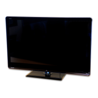
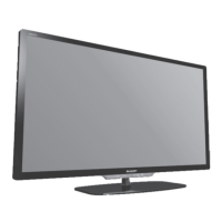
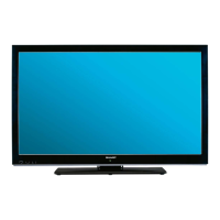
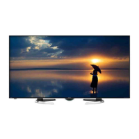
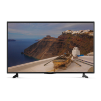
LCD COLOR TELEVISION
LC-40LE820UN
LC-46LE820UN
LC-52LE820UN
LC-60LE820UN
MODELS







 Loading...